Heat exchange device
- Summary
- Abstract
- Description
- Claims
- Application Information
AI Technical Summary
Benefits of technology
Problems solved by technology
Method used
Image

Examples
first embodiment
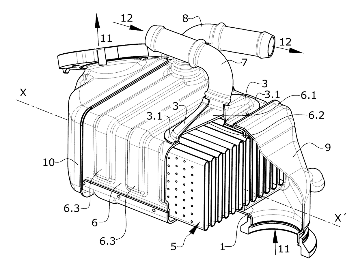
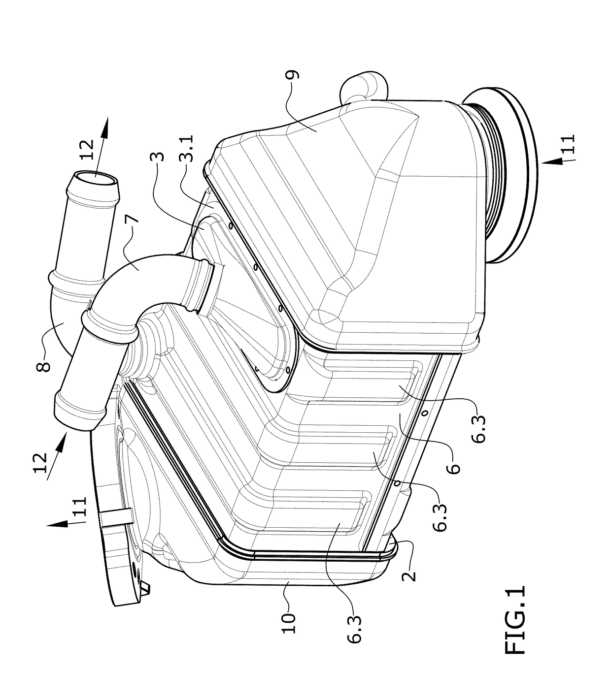
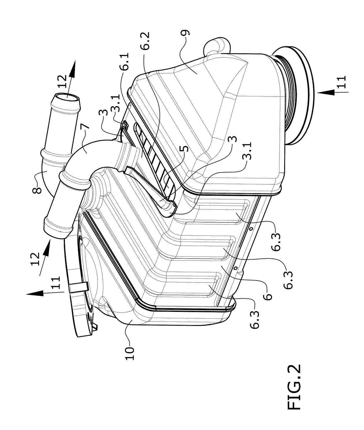
[0026] it can be seen that the closure is established for a tube bundle of flat tubes by means of the use of baffles.
second embodiment
[0027] it can be seen that the closure is established for a tube bundle, wherein the tubes are formed by stacked plates, by means of a configuration of the tubes in the tube bundle in which the ends of the tubes are expanded. On the stacking of the tubes, such tubes are supported on one another in the expanded area and leave in the intermediate area passage channels for the second fluid with which the transfer of heat is established. This second configuration prevents using baffles and maximizes the area for entry into the tubes of the tube bundle.
[0028]In any case, the inlet for the first fluid is formed by the set of openings of the tube bundle which allow the entry of hot gas, and the outlet for the first fluid is formed by the set of openings of the tube bundle which allow the exit of said hot gas.
[0029]The second fluid entering the shell accesses the inside of same through a tubular inlet segment and exits through a tubular outlet segment. These tubular segments can be, for exa...
PUM
 Abstract
Description
Claims
Application Information
 - R&D
- Intellectual Property
- Life Sciences
- Materials
- Tech Scout
- Unparalleled Data Quality
- Higher Quality Content
- 60% Fewer Hallucinations
Browse by: Latest US Patents, China's latest patents, Technical Efficacy Thesaurus, Application Domain, Technology Topic, Popular Technical Reports.
© 2025 PatSnap. All rights reserved.Legal|Privacy policy|Modern Slavery Act Transparency Statement|Sitemap|About US| Contact US: help@patsnap.com