
Method for Engineering a Method- or Process-Engineering Plant, Function Module and Stored Program Control

Active Publication Date: 2017-11-23
SIEMENS AG
View PDF4 Cites 3 Cited by
  • Summary
  • Abstract
  • Description
  • Claims
  • Application Information

AI Technical Summary

Benefits of technology

The invention provides a method for low-cost engineering of a method-or process-engineering plant with at least one function module. The function module can be easily integrated into the plant without requiring detailed knowledge of the entire project plan. The user program for the function module is written in a way that allows for easy customization based on the user's requirements. The manufacturer of the function module provides a tool for engineering the SPC (Supervisory Control and Data Acquisition) that allows for easy customization of the function module. The tool compiles a program that can be downloaded and used in the SPC. This approach ensures that the know-how of the manufacturer is protected. The plant-engineering tool simplifies the engineering of the plant by providing knowledge of the parameters and the method for configuring the function module. The tool allows for real-time changes to the function module during plant operation, reducing interruptions and costly downtime.

Problems solved by technology

To engineer the plant, the user then disadvantageously has to be able to hold available and use engineering tools from all the manufacturers of controls used in function modules of the respective plant.
The integration of the function modules and the modification or adaptation of functions of the modules at the time of their integration in the plant are therefore disadvantageously associated relatively high costs.
This has the drawback in that it is once again necessary to hold available configuration devices from the different manufacturers to engineer the plant.

Method used


Image

  • Method for Engineering a Method- or Process-Engineering Plant, Function Module and Stored Program Control
  • Method for Engineering a Method- or Process-Engineering Plant, Function Module and Stored Program Control
  • Method for Engineering a Method- or Process-Engineering Plant, Function Module and Stored Program Control

Examples


Embodiment Construction

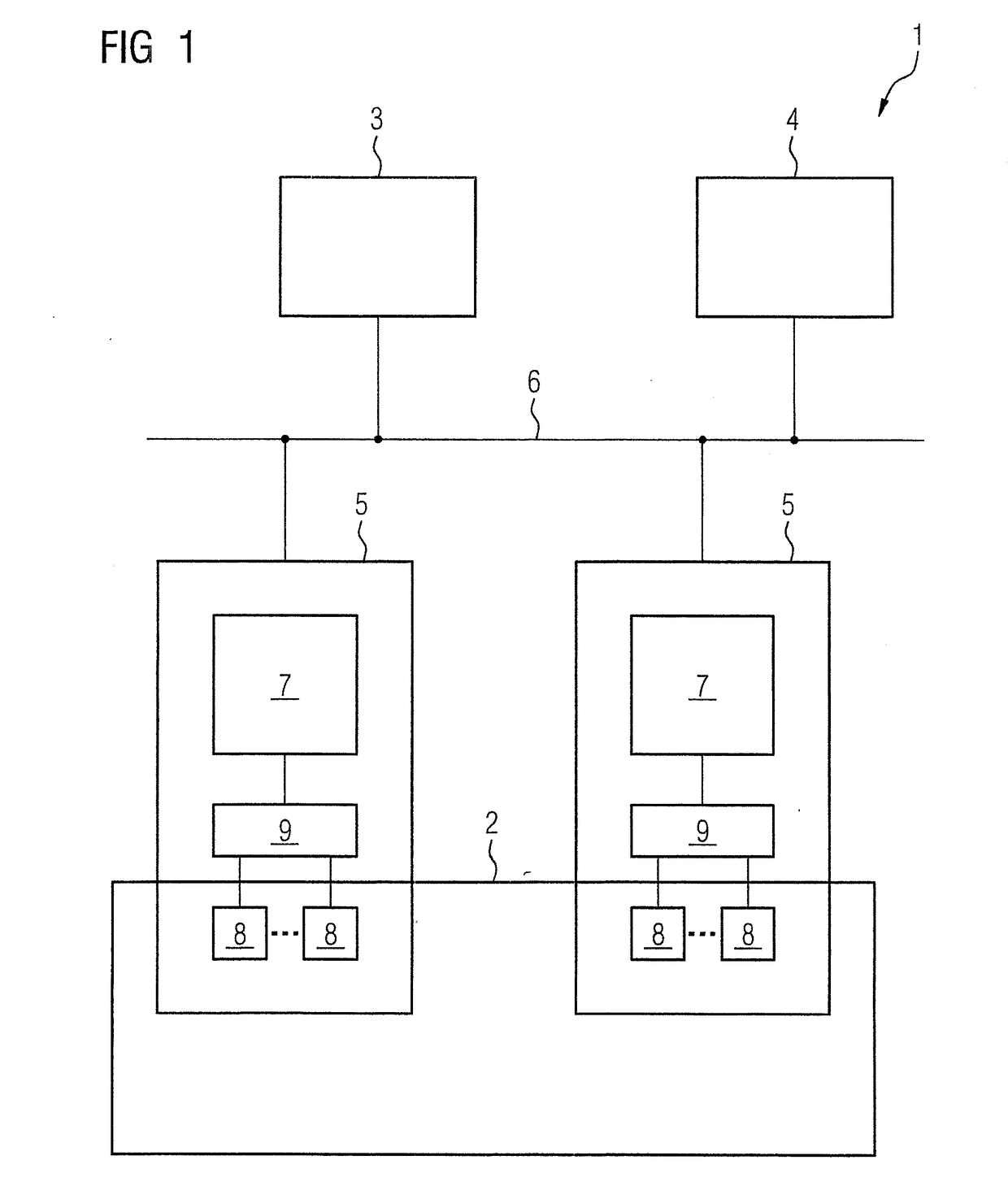
[0018]FIG. 1 is a simplified schematic depiction of an exemplary plant 1 in which a process 2 is controlled by an automation system. The automation system comprises an engineering tool 3, an operating and monitoring device 4 and a plurality of function modules 5 connected to one another via a bus system 6 for data communication. For purposes of clarity, only two function modules 5 are depicted. The function modules 5 control the process 2 in accordance with configurable user programs executing in stored program controls 7 of the modules 5. Moreover, in order to control the process 2, use is made of various field devices 8, which, for example, are connected via devices 9, i.e., decentralized I / O devices, to the controls 7. The field devices 8 can be measuring transducers used to acquire process variables, such as the temperature, pressure, flow rate, fill level, density or gas concentration of a medium. The field devices 8 can also be actuators that are able to influence the process ...


PUM


Abstract

A method for engineering a method-or process-engineering plant with at least one function module, a corresponding function module and a stored program control, wherein the function module includes the stored program control and the method-or process-engineering module that can be controlled or regulated thereby fur use as part of the plant, where a parameter-configurable user program is loaded into the stored program control, and information for the integration of the function module in a file is provided, during engineering of the plant, which defines the parameters for the application-specific configuration of the function module via a plant-engineering tool and stored via an interface specified in a formal description language, for configuration of the user program, in a memory area of the control such that an engineering tool, which is specific to the respective stored program controls used within function modules, is advantageously no longer required.

Description

BACKGROUND OF THE INVENTION1. Field of the Invention[0001]The invention relates to a method for engineering a method-or process-engineering plant with at least one function module, where the function module comprises a stored program control (SPC) and a method-or process-engineering module that can be controlled and / or regulated via the SPC for use as a part of a plant. The invention further relates to a function module for use in a method of this kind and an SPC for the function module of this kind.2. Description of the Related Art[0002]In order to perform engineering of the automation of a method-or process-engineering plant, hereinafter plant for short, typically in a plant engineering tool, in a first step, the structure of the plant is acquired and the tool is used to compile a P&I diagram of the plant or of parts of the plant by linking graphic process objects. The graphic process objects represent the components required for the operation of the plant, such as sensors, motors...

Claims


Application Information

Patent Timeline
IPC IPC(8): G05B19/418
CPCG05B2219/36186G05B19/4187G05B19/0426G05B2219/23146G05B19/056
Inventor MAURMAIER, MATHIASSTUTZ, ANDREAS
Owner SIEMENS AG
Learn More