Liquid ejection head, liquid ejection apparatus, and liquid ejection head manufacture method

Active Publication Date: 2017-11-30
CANON KK
View PDF6 Cites 7 Cited by
  • Summary
  • Abstract
  • Description
  • Claims
  • Application Information

AI Technical Summary

Benefits of technology

The present invention provides a liquid ejection head with improved airtightness. This is achieved by sealing the gap between the cover member and the retention member, which allows the cap member to function effectively. In simple terms, the invention ensures that the liquid ejection head is well-sealed and can perform its duties effectively.

Problems solved by technology

However, a manufacture variation of cover members and a manufacture variation of member of the printing head for forming an attachment face on which the cover member is attached may cause a risk where a gap is caused between the cover member and the member to which the cover member is attached.
In particular, in the case of the specification of U.S. Pat. No. 9,211,718 disclosing a long printing head including a plurality of printing element substrates, a long cover member is required and the member of the printing head for forming an attachment face on which the cover member is attached requires a plurality of members, which tends to cause a gap between the cover member and the attachment face.
When the attachment face for the cover member has a wiring member, the wiring member causes a concavo-convex shape, which tends to cause a gap between the cover member and the attachment face.

Method used


Image

  • Liquid ejection head, liquid ejection apparatus, and liquid ejection head manufacture method
  • Liquid ejection head, liquid ejection apparatus, and liquid ejection head manufacture method
  • Liquid ejection head, liquid ejection apparatus, and liquid ejection head manufacture method

Examples


first embodiment

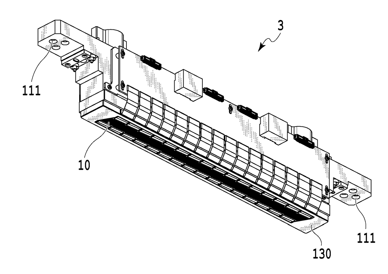
[0074]FIG. 12A to FIG. 14C are diagrams to explain a comparison example of the liquid ejection head. FIG. 12A is a perspective view illustrating the liquid ejection head. FIG. 12B is a top view of the liquid ejection head prior to being attached with the cover member 130. FIG. 12C is an arrow view along a direction XIIC of FIG. 12B. FIG. 13A is a top view illustrating the liquid ejection head being attached with the cover member 130. FIG. 13B is an arrow view along a direction XIIIB of FIG. 13A. FIG. 13C is an arrow view along a line XIIIC-XIIIC of FIG. 13A. FIG. 14A is a side view illustrating the liquid ejection head abutted to the cap member 1007. FIG. 14B is a diagram similar to FIG. 13C when the liquid ejection head is abutted to the cap member 1007. FIG. 14C illustrates the leakage status of the negative pressure in the cap member 1007 when the cap member 1007 is abutted to the cover member 130 and the interior of the cap member 1007 is sucked by a not-shown suction mechanism....

second embodiment

[0079]In the first embodiment, the cap member 1007 abutted to the cover member 130 can avoid the communication of the space in the cap member 1007 with atmospheric air as in the comparison example of FIG. 14B. This can consequently maintain the sealed space of the cap member 1007 to perform a stable recovery operation.

[0080]In order to suppress the expansion and contraction of the members constituting the liquid ejection head in a heating step, a sealing member that cures at a normal temperature can be used as the sealing member 54 to thereby avoid the influence by heat during the heating step. However, when all of the regions among a plurality of separate first flow path members 50 are sealed by the sealing member 54, not a little influence is caused by the curing and shrinkage of the sealing member 54 itself. Furthermore, there is a risk where the sealing member 54 is swollen due to the influence by the attachment of ink used in the liquid ejection head and the usage environment. ...

third embodiment

[0085]In the above-described first and second embodiments, prior to the attachment of the cover member 130, the sealing member 54 is used to seal a part of the interior of the cap member 1007 communicating with atmospheric air in the capping status. As described above, the part in which the interior of the cap member 1007 communicates with the atmospheric air is the gap between the first flow path members 50 and the gap between the cover member 130 and the second flow path member 60. Thus, such a gap can be sealed in the first and second embodiments.

[0086]On the other hand, there may be a case where variation (physical property variation) is caused in the part accuracy of the plurality of first flow path members 50, the adhesion accuracy thereof, the part accuracies of the cover member 130 and the second flow path member 60, the adhesion accuracy thereof, and the viscosity of each manufacture lot of the sealing member 54 for example. Such a variation causes a risk where a position a...


PUM


Abstract

In order that the interior of a cap member, in a case where the cap member abuts to a cover member, is allowed to have improved airtightness so that the cap member can sufficiently function, a sealing member is used to seal between the cover member and first and second flow path members for retaining the cover member.

Description

BACKGROUND OF THE INVENTIONField of the Invention[0001]The present invention relates to a liquid ejection head, a liquid ejection apparatus, and a liquid ejection head manufacture method by which liquid such as ink is ejected.Description of the Related Art[0002]The specification of U.S. Pat. No. 9,211,718 discloses an inkjet printing head to eject liquid ink as a liquid ejection head. In the printing head, a plurality of printing element substrates having elements for ejecting liquid through ejection openings are arranged. A cover member is provided so as to surround the plurality of printing element substrates. When a surface of this cover member is abutted to (capped with) a cap member and the interior of the cap member comes into an airtight status, ink can be suppressed from being evaporated from the ejection opening of the printing head. The suction of the cap interior can provide a recovery processing to suck and discharge ink from the ejection opening of the printing head.[00...

Claims


Application Information

Patent Timeline
IPC IPC(8): B41J2/165B41J2/16
CPCB41J2/16505B41J2/162B41J2/1632B41J2/14024B41J2/14072B41J2/16508B41J2/1652B41J2/16532B41J2/16585B41J2002/14459B41J2202/12B41J2202/20
Inventor TAMENAGA, ZENTAROIWANAGA, SHUZOOKUSHIMA, SHINGO
Owner CANON KK
Why Eureka
Try Eureka