Continuous monitoring of drive amplitude in vibrating microelectromechanical gyroscopes

a microelectromechanical and drive amplitude technology, applied in the direction of speed measurement using gyroscopic effects, instruments, surveying and navigation, etc., can solve the problem of erroneous measurement, change the sensitivity of the gyroscope, complicated sense oscillation movemen

Active Publication Date: 2017-11-30
MURATA MFG CO LTD
View PDF2 Cites 9 Cited by
  • Summary
  • Abstract
  • Description
  • Claims
  • Application Information

AI Technical Summary

Problems solved by technology

While the drive oscillation is set by the drive signal in the manner described above, the sense oscillation is a more complicated movement.
An unintended and undetected change in drive oscillation amplitude would change the sensitivity of the gyroscope and produce erroneous measurement results.
Drive oscillation mechanics may also change due to various unexpected faults during operation.
Production defects or mechanical wear in the active parts of the gyroscope or the bonds between them can affect its operation either gradually and suddenly.
The problem with this prior art solution is that it requires separate self-test excitation electronics and a separate self-test excitation actuator.
A gyroscope with this self-test functionality therefore requires more chip area and consumes more current than a gyroscope without self-test functionality.
The additional excitation electronics and actuator also introduce additional complexity and a potential source of measurement error.
The problem with this solution is that additional electrodes and circuitry have to be introduced for monitoring the drive oscillation.
Furthermore, there is a risk of crosstalk between the drive signal and the drive monitoring signal, which increases the risk of measurement errors.

Method used


Image

  • Continuous monitoring of drive amplitude in vibrating microelectromechanical gyroscopes
  • Continuous monitoring of drive amplitude in vibrating microelectromechanical gyroscopes
  • Continuous monitoring of drive amplitude in vibrating microelectromechanical gyroscopes

Examples


example 1

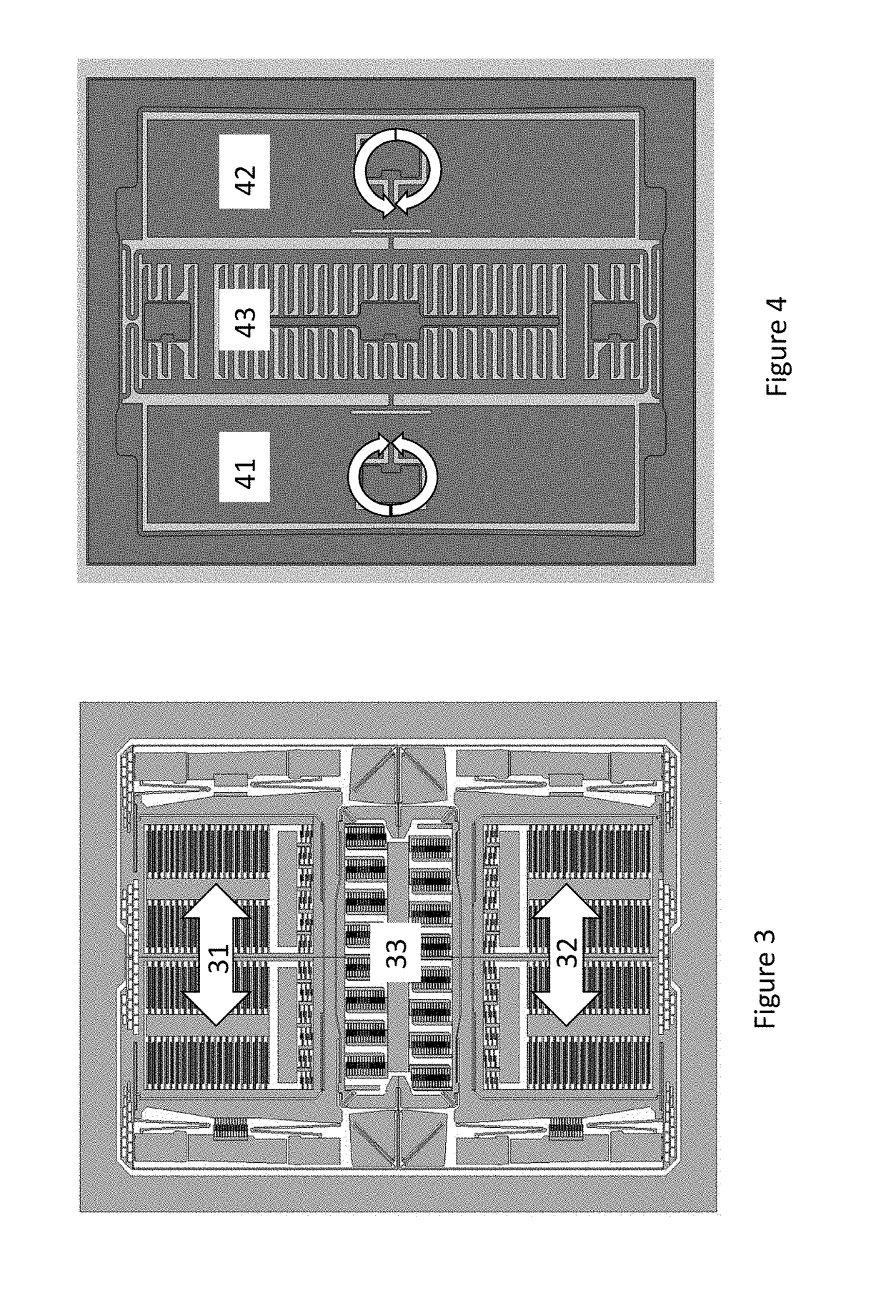
[0048]FIGS. 6a-6e illustrate the working principle of a first exemplary gyroscope structure. The gyroscope is of the kind illustrated in FIG. 3, where two mass elements are driven in linear oscillation. The drive oscillation frequency ωD may, for example, be 8 kHz in gyroscopes of this kind. The second harmonic frequency would then be 16 kHz.

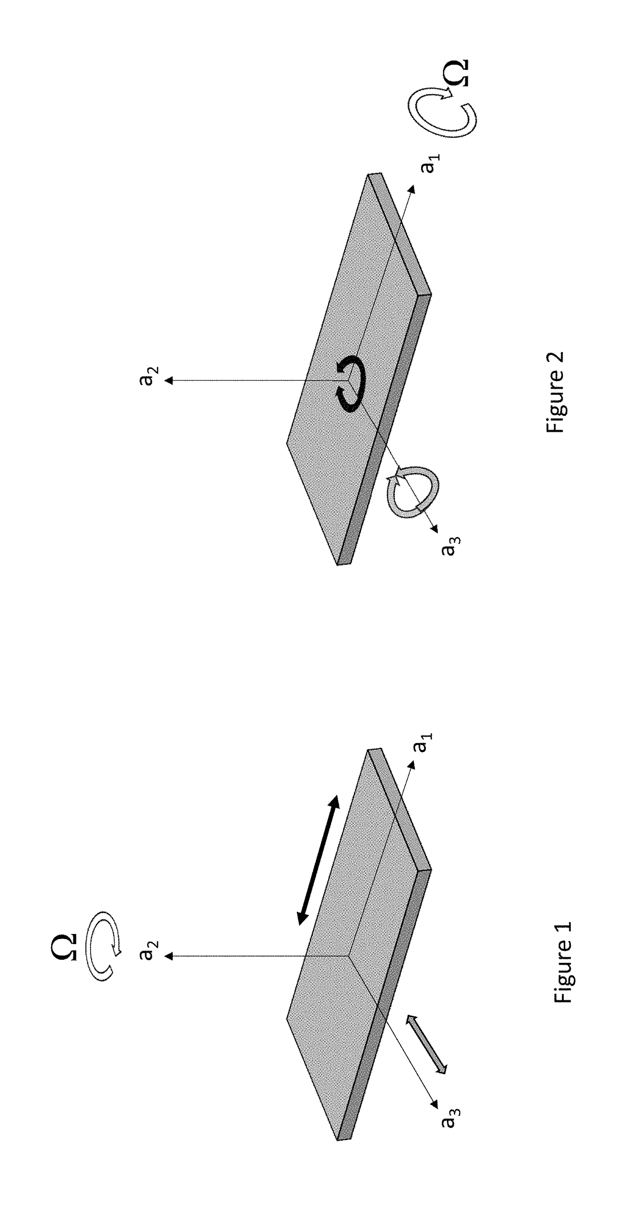
[0049]When this gyroscope undergoes angular rotation the Coriolis force actuates a linear translation perpendicular to the drive oscillation, as FIG. 1 illustrates. The axes shown in FIG. 1 are also indicated in FIGS. 6a-6e.

[0050]FIG. 6a shows a mass element 611 with sense finger electrodes 614 surrounding a fixed center electrode 641 with fixed finger electrodes 644. The term “sense electrodes” in this disclosure covers both sense finger electrodes and fixed finger electrodes. The mass element 611 is suspended from springs (not shown) attached to a frame (not shown). The fixed center electrode 641 and fixed finger electrodes 644 are fixed to t...

example 2

[0068]FIGS. 7a-7b illustrate the working principle of a second exemplary gyroscope structure. The gyroscope type is illustrated in FIG. 4, where two mass elements are driven in rotational oscillation. When this gyroscope undergoes angular rotation the Coriolis force actuates a rotation out of the substrate plane, as explained earlier.

[0069]This rotation out of the substrate plane can be detected through a differential capacitance measurement utilizing plate-shaped sense electrodes 741 and 742 above and below the mass element 711, as illustrated in FIG. 7a. The surface areas of the electrodes and the mass element have been drawn exactly equal in FIG. 7a, but the apparatus and method of this disclosure can be implemented also with electrode areas smaller or larger than the area of the sense mass.

[0070]When the mass element 711 is in drive motion, it rotates back and forth about axis a2. FIG. 7b shows the positions of the top sense electrode 741 and the mass element 711 projected onto ...


PUM


Abstract

The disclosure relates to a microelectromechanical gyroscope comprising at least one mass element, a drive actuator and sense electrodes. The at least one mass element is configured to be driven by the drive actuator into oscillating movement with a drive oscillation frequency ωD, and the sense electrodes are configured to produce a sense signal from the oscillating movement of the at least one mass element. The gyroscope control circuit comprises an amplitude detection unit which detects a sense signal amplitude at the frequency 2ωD. This amplitude yields a measure of drive oscillation amplitude. Amplitude detection at the frequency ωD yields a measure of angular rotation rate.

Description

BACKGROUNDField[0001]The present invention relates to vibrating microelectromechanical (MEMS) gyroscopes and to continuous monitoring of their operation.Brief Description of the Related Art[0002]MEMS gyroscopes use the Coriolis Effect to measure angular velocity. In a vibrating MEMS gyroscope a mass element is driven into oscillating movement by an actuating drive force. This oscillation will be called “drive oscillation” in this disclosure and it can be either linear or rotational. FIG. 1 illustrates a mass driven in linear oscillation along its primary axis a1, while FIG. 2 illustrates a mass driven in rotational oscillation about its primary axis a2. The drive oscillation is indicated with a solid black arrow in both figures. The actuating drive force can be generated, for example, with an electrostatic, magnetic or piezoelectric actuator.[0003]A microelectromechanical gyroscope may comprise a reference frame to which one or more mass elements are connected with spring structures...

Claims


Application Information

Patent Timeline
Patent Type & Authority Applications(United States)
IPC IPC(8): G01C19/5712G01C19/5733
CPCG01C19/5733G01C19/5712G01C19/5726G01C19/574
Inventor TORMALEHTO, KIMMO
Owner MURATA MFG CO LTD
Why Eureka
Try Eureka