
Devices and methods of forming low resistivity noble metal interconnect with improved adhesion

a noble metal and interconnecting material technology, applied in the field of semiconductor devices and methods of fabricating semiconductor devices, can solve the problems of delamination of barrier layer and interconnect material from the device, increasing the resistivity of copper lines, and decreasing the performance of nodes

Inactive Publication Date: 2017-11-30
GLOBALFOUNDRIES INC
View PDF8 Cites 7 Cited by
  • Summary
  • Abstract
  • Description
  • Claims
  • Application Information

AI Technical Summary

Benefits of technology

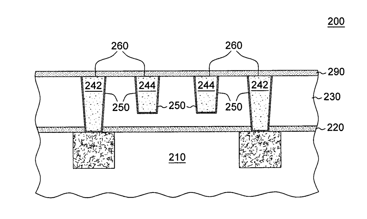
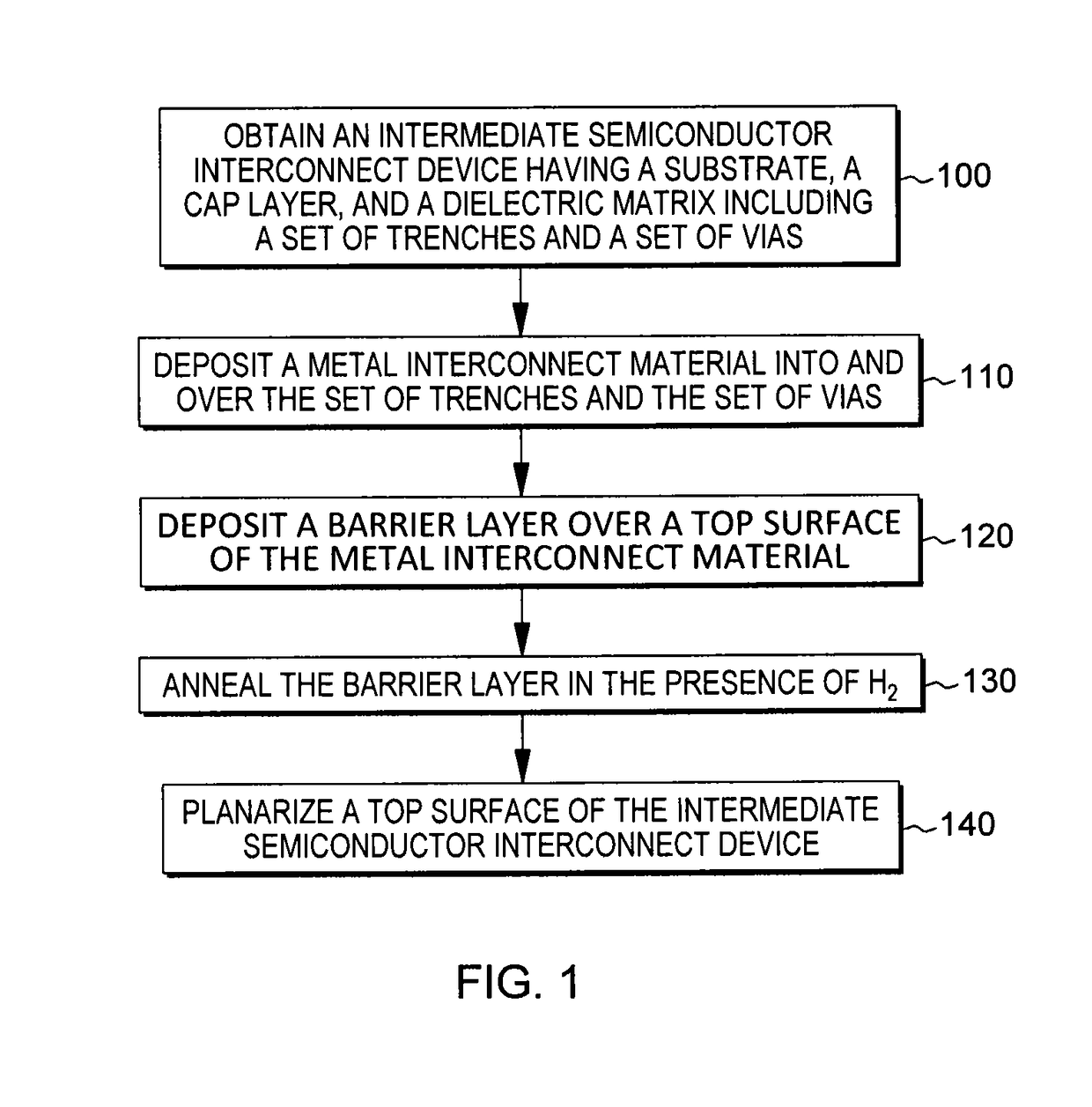
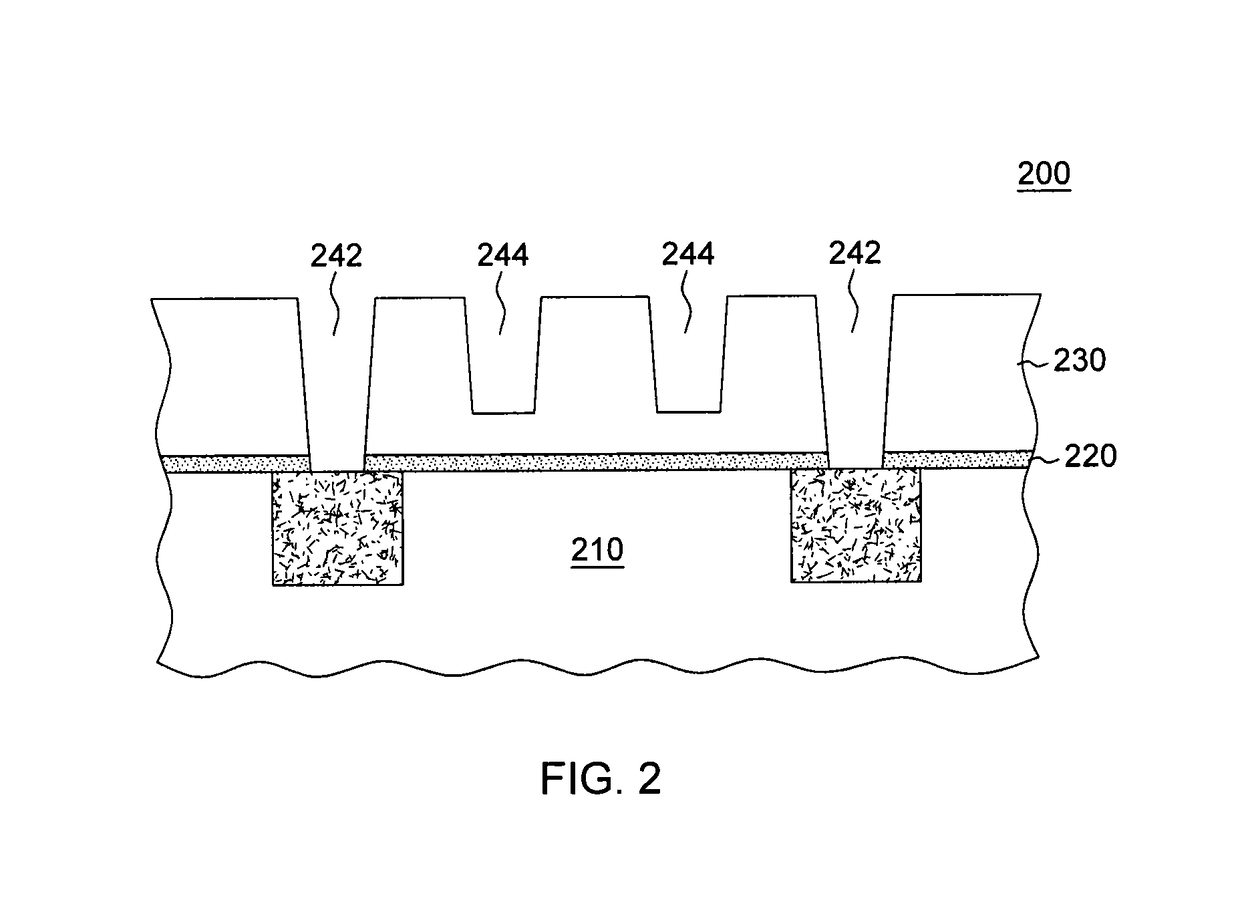
The present invention provides an improved method for making semiconductor interconnect devices by depositing a metal interconnect material directly over a dielectric matrix including a set of trenches and a set of vias, annealing a barrier layer to diffuse it to the bottom surface of the metal interconnect material, planarizing the top surface of the device to remove excess metal interconnect material, and depositing a dielectric cap over the device. This process allows for better control of the metal fill and planarization of the device, resulting in improved performance and reliability. An intermediate device is also provided that includes a substrate, a cap layer, and a dielectric matrix including a set of trenches and a set of vias, a barrier layer over a top surface of the dielectric matrix, a metal interconnect material directly over the barrier layer, wherein the metal interconnect material fills the set of trenches and the set of vias, and wherein the barrier layer is annealed, and a dielectric cap over the intermediate semiconductor interconnect device.

Problems solved by technology

For 5 nm and beyond nodes, with the continually increasing demand for smaller circuit structures and faster device performance, copper line resistivity begins to climb, decreasing the performance of the nodes.
However, at these sizes, previous methods of lining trenches and vias can cause delamination of the barrier layer and the interconnect material from the device.

Method used


Image

  • Devices and methods of forming low resistivity noble metal interconnect with improved adhesion
  • Devices and methods of forming low resistivity noble metal interconnect with improved adhesion
  • Devices and methods of forming low resistivity noble metal interconnect with improved adhesion

Examples


Embodiment Construction

[0019]Aspects of the present invention and certain features, advantages, and details thereof, are explained more fully below with reference to the non-limiting embodiments illustrated in the accompanying drawings. Descriptions of well-known materials, fabrication tools, processing techniques, etc., are omitted so as to not unnecessarily obscure the invention in detail. It should be understood, however, that the detailed description and the specific examples, while indicating embodiments of the invention, are given by way of illustration only, and are not by way of limitation. Various substitutions, modifications, additions and / or arrangements within the spirit and / or scope of the underlying inventive concepts will be apparent to those skilled in the art from this disclosure. Note also that reference is made below to the drawings, which are not drawn to scale for ease of understanding, wherein the same reference numbers used throughout different figures designate the same or similar ...


PUM


Abstract

Devices and methods of fabricating integrated circuit devices for forming low resistivity interconnects with improved adhesion are provided. One method includes, for instance: obtaining an intermediate semiconductor interconnect device having a substrate, a cap layer, and a dielectric matrix including a set of trenches and a set of vias; depositing a metal interconnect material directly over and contacting a top surface of the dielectric matrix, wherein the metal interconnect material fills the set of trenches and the set of vias; depositing a barrier layer over a top surface of the device; annealing the barrier layer to diffuse the barrier layer to a bottom surface of the metal interconnect material; planarizing a top surface of the intermediate semiconductor interconnect device; and depositing a dielectric cap over the intermediate semiconductor interconnect device.

Description

FIELD OF THE INVENTION[0001]The present invention relates to semiconductor devices and methods of fabricating semiconductor devices, and more particularly, to devices and methods of forming low resistivity metal interconnects having noble metals with an improved adhesion.BACKGROUND OF THE INVENTION[0002]For 5 nm and beyond nodes, with the continually increasing demand for smaller circuit structures and faster device performance, copper line resistivity begins to climb, decreasing the performance of the nodes. The development of 5 nm nodes and smaller will likely require lowering the resistivity of the lines in the nodes. However, at these sizes, previous methods of lining trenches and vias can cause delamination of the barrier layer and the interconnect material from the device.[0003]Therefore, it may be desirable to develop methods of fabricating nodes with lines that have a lower resistivity than copper at such a small size and that have an improved adhesion.BRIEF SUMMARY[0004]The...

Claims


Application Information

Patent Timeline
IPC IPC(8): H01L23/532H01L21/768H01L21/311H01L23/528H01L23/522H01L21/285
CPCH01L23/53252H01L23/528H01L23/5226H01L21/76877H01L21/7685H01L21/76864H01L21/28556H01L21/76834H01L21/7682H01L21/31111H01L23/5329H01L21/2855H01L21/7684H01L21/76838H01L23/53242H01L23/5222H01L23/53295H01L21/76843H01L21/76831H01L21/76867
Inventor ZHANG, XUNYUANMONT, FRANK W.RYAN, ERROL TODD
Owner GLOBALFOUNDRIES INC
Learn More