Pressure monitoring apparatus

a technology of pressure monitoring and pressure monitoring, which is applied in the direction of mechanical equipment, instruments, pumps, etc., can solve the problems of affecting membranes or compressors that cannot be damaged, and cannot ensure the operation of membrane compressors. unperturbed, the effect of reducing the installation volume and facilitating operation

Inactive Publication Date: 2017-12-07
ANDREAS HOFER HOCHDRUCKTECHN
View PDF0 Cites 0 Cited by
  • Summary
  • Abstract
  • Description
  • Claims
  • Application Information

AI Technical Summary

Benefits of technology

[0013]It is advantageously provided that the shutoff valves are implemented by a 3/2 way valve. The 3/2 way valve simplifies the switching possibilities of the flow path. In this way, it is possible to automatically block only the first flow path or only the second flow path. Appropriately, at least one flow path at a time is consequently opened so that measurements can be taken. The option of opening two flow paths would lead to the pressure transducer continuously receiving signals, since both a pressure increase, and also a pressure reduction are possible when the two flow paths are opened. Moreover, the use of a 3/2 way valve also leads to the pressure monitoring apparatus being able to have altogether a relatively small installation volume.
[0014]For easier operation of the pressure monitoring apparatus, there is a pressure display apparatus which displays the values which have been measured by the pressure transducer. The pressure display apparatus can preferably be a visual indication, for example, a display, so that the current pressure value can be promptly and easily read off on site. In addition, however, an acoustic indication is possible with which in addition a warning signal is delivered when a boundary value is reached.
[0015]Another advantageous configuration of the invention calls for there to be a programmable control for control and/or adjustment of...

Problems solved by technology

In doing so in particular gases can be contaminated by lubricants or other substances.
If this is not the case, unperturbed operation of the membrane compressor cannot be ensured.
In the worst case the membrane or the...

Method used


Image

  • Pressure monitoring apparatus
  • Pressure monitoring apparatus
  • Pressure monitoring apparatus

Examples


Embodiment Construction

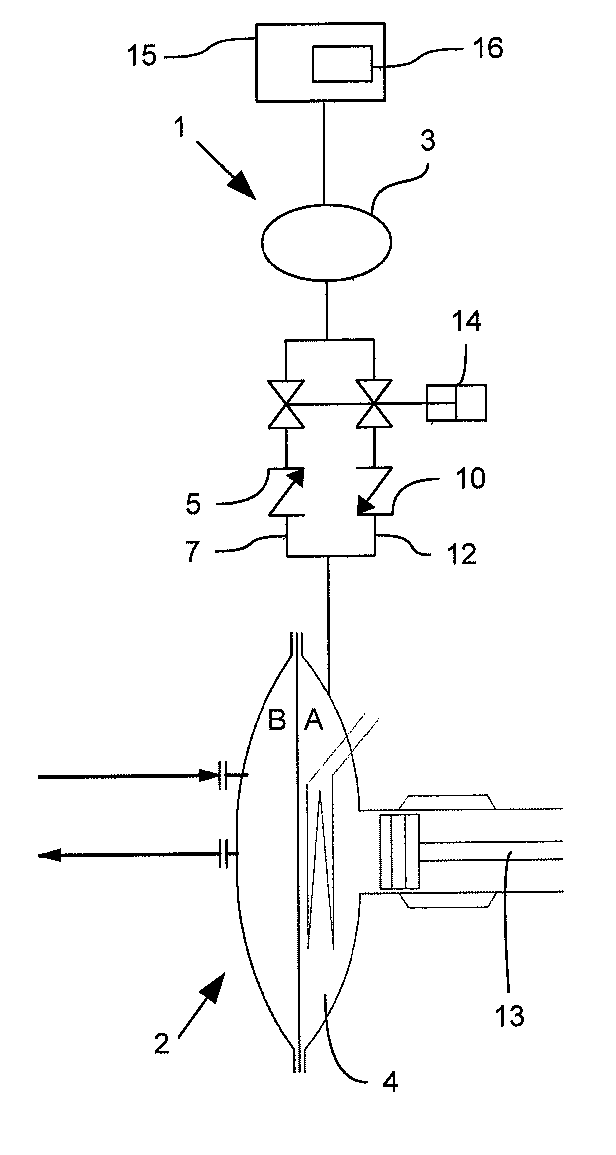
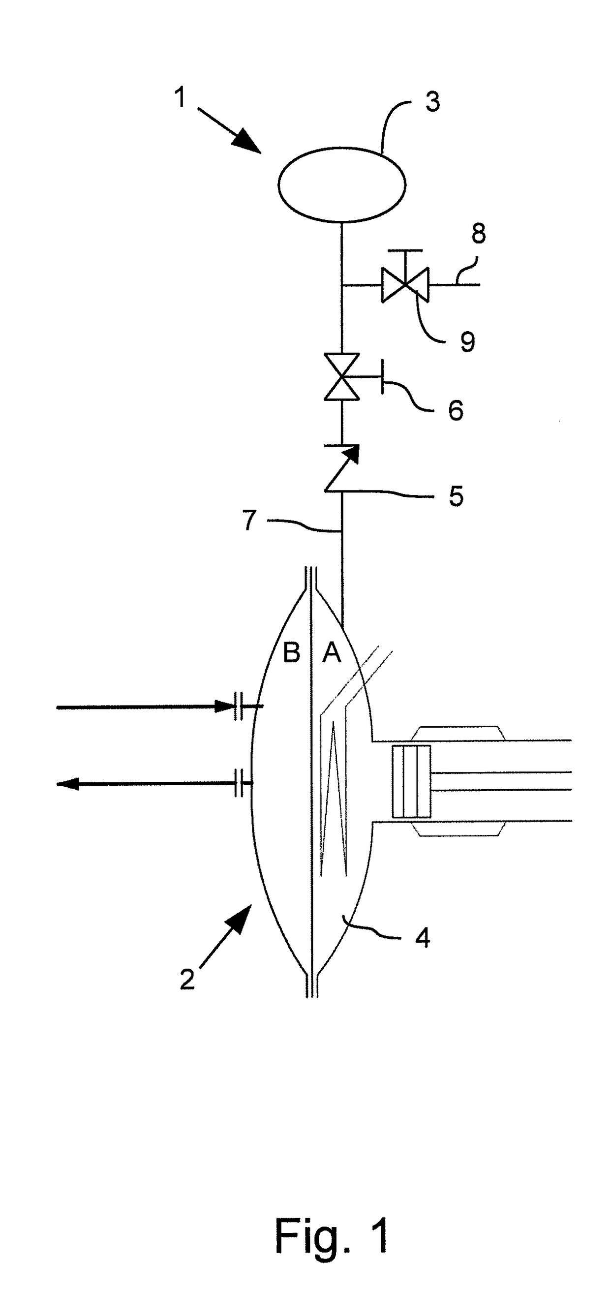
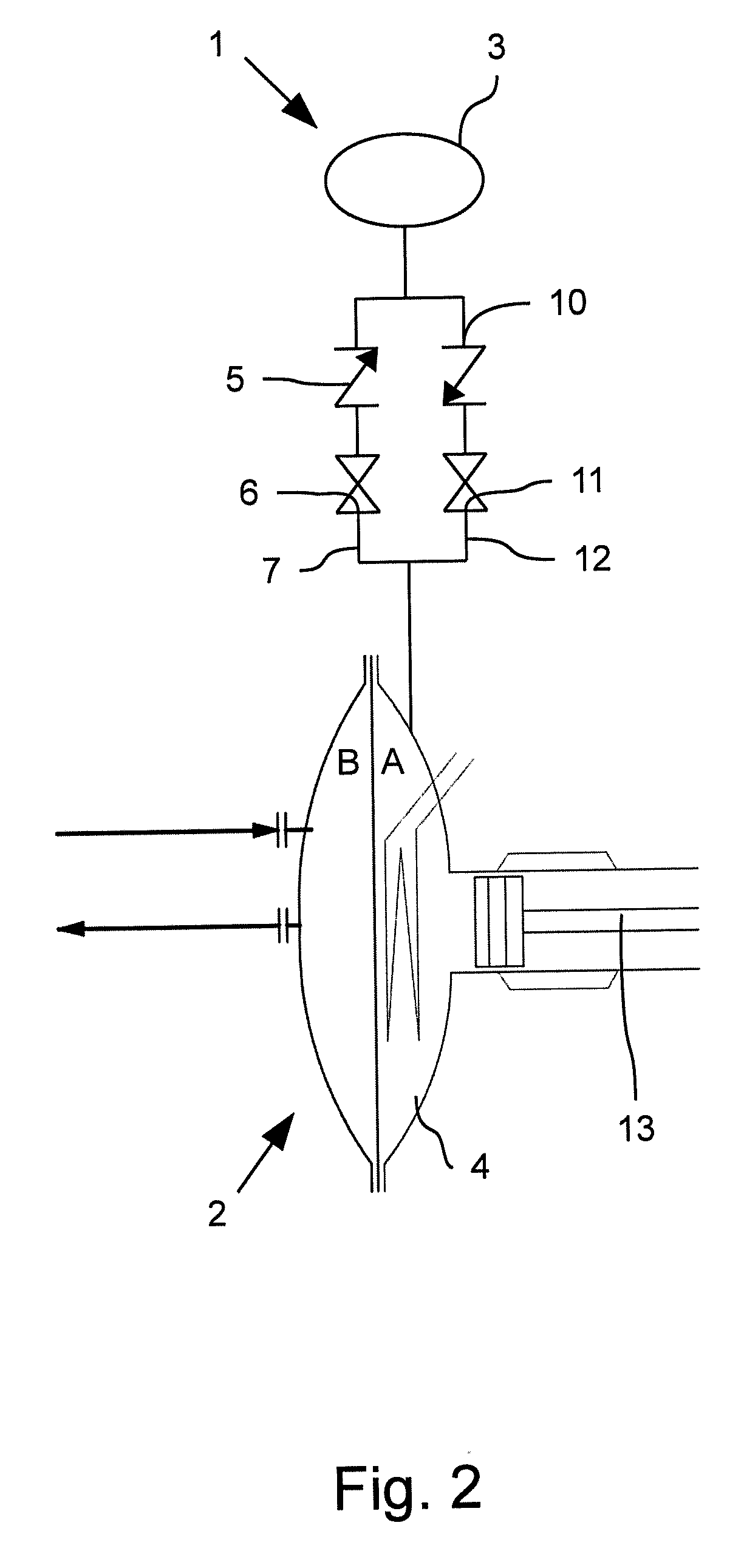
[0027]FIG. 1 is a schematic representation of a pressure monitoring apparatus 1 known from the prior art. The illustrated pressure monitoring apparatus 1 can be used to monitor the pressure in a membrane compressor 2 with an oil side A and a gas side B separated by a membrane. For this purpose, there is a pressure transducer 3 which measures the pressure in the volume 4 on the oil side A of the membrane compressor 2. Between the volume 4 and the pressure transducer 3, there are a nonreturn valve 5 and a shutoff valve 6 in the flow path 7 from the volume 4 to the pressure transducer 3. Downstream of the shutoff valve 6 in the direction toward the pressure transducer 3 is a branch 8 in which there is another shutoff valve 9.

[0028]The nonreturn valve 5 blocks flow in the direction from the pressure transducer 3 to the volume 4, i.e., the nonreturn valve 5 opens in the direction from the volume 4 to the pressure transducer 3. As long as the pressure in the volume 4 is greater than the p...


PUM


Abstract

A pressure monitoring apparatus for a membrane compressor, with at least one pressure transducer for recording the pressure within a certain volume, with at least one nonreturn valve and with at least one shutoff valve, for blocking of the nonreturn valve, the shutoff valve and the nonreturn valve each being located in a flow path through which a medium can flow between the volume and the pressure transducer. A pressure monitoring unit delivers exact measured values and which can be economically implemented is achieved by there being at least two nonreturn valves which are located anti-parallel in respective flow paths, the first nonreturn valve blocking in the flow direction from the volume to the pressure transducer and the second nonreturn valve blocking in the flow direction from the pressure transducer to the volume, and by there being at least two shutoff valves for blocking a respective flow path.

Description

BACKGROUND OF THE INVENTIONField of the Invention[0001]The invention relates to a pressure monitoring apparatus, in particular for a compressor, with at least one pressure transducer for recording the pressure within a certain volume, with at least one nonreturn valve and with at least one shutoff valve for blocking of the nonreturn valve, the shutoff valve and the nonreturn valve each being located in a flow path through which a medium can flow between the volume being monitored and the pressure transducer.Description of Related Art[0002]Pressure monitoring apparatus are known from the prior art and are often used. In many, technical domains for example pure gases are required which are sold as a product or are used in industrial installations for other purposes. Such technical gases, for example cooling gases, are routed in a continuous circuit in order on the one hand to enable economical operation of an industrial installation and on the other to make the gases available at the ...

Claims


Application Information

Patent Timeline
IPC IPC(8): F04B51/00F04B45/04G01L19/00G01L19/08
CPCF04B51/00G01L19/0007G01L19/086F04B45/04F04B39/04F04B43/0081F04B45/0533F04B45/0536F04B49/22F04B2201/0401F04B2205/03
Inventor DEHNEN, MANFRED
Owner ANDREAS HOFER HOCHDRUCKTECHN
Why Eureka
Try Eureka