Seismic Source Installation/Anchoring System and Method

Inactive Publication Date: 2017-12-07
GREENPOWER USA
View PDF0 Cites 4 Cited by
  • Summary
  • Abstract
  • Description
  • Claims
  • Application Information

AI Technical Summary

Benefits of technology

The present invention provides a simple and cost-effective way to connect vibrations from a seismic source to the ground. This is achieved by using a screw in piling which is inserted into the soil using a backhoe. An elastic mounting system attaches the seismic source to the top of the screw in piling and when the source is activated, the energy is transferred down the screw and into the soil. This invention offers an improved method for tying seismic sources to the ground.

Problems solved by technology

Although commonly used, this method requires heavy equipment / vehicles that are expensive and difficult to transport, and in addition, can be very lossy depending upon the firmness of the surface.
This provides excellent coupling but digging the holes and cementing the source is time consuming, expensive, and makes the source inaccessible for repair or relocation.
This method ensures the sources are accessible for repairs and can be relocated, however, the pillars are time consuming and expensive to install, their weight can reduce the magnitude of the vibrations going into the earth, and the depth of the pillar may not be sufficient to be in contact with good load bearing soil.

Method used


Image

  • Seismic Source Installation/Anchoring System and Method
  • Seismic Source Installation/Anchoring System and Method
  • Seismic Source Installation/Anchoring System and Method

Examples


Embodiment Construction

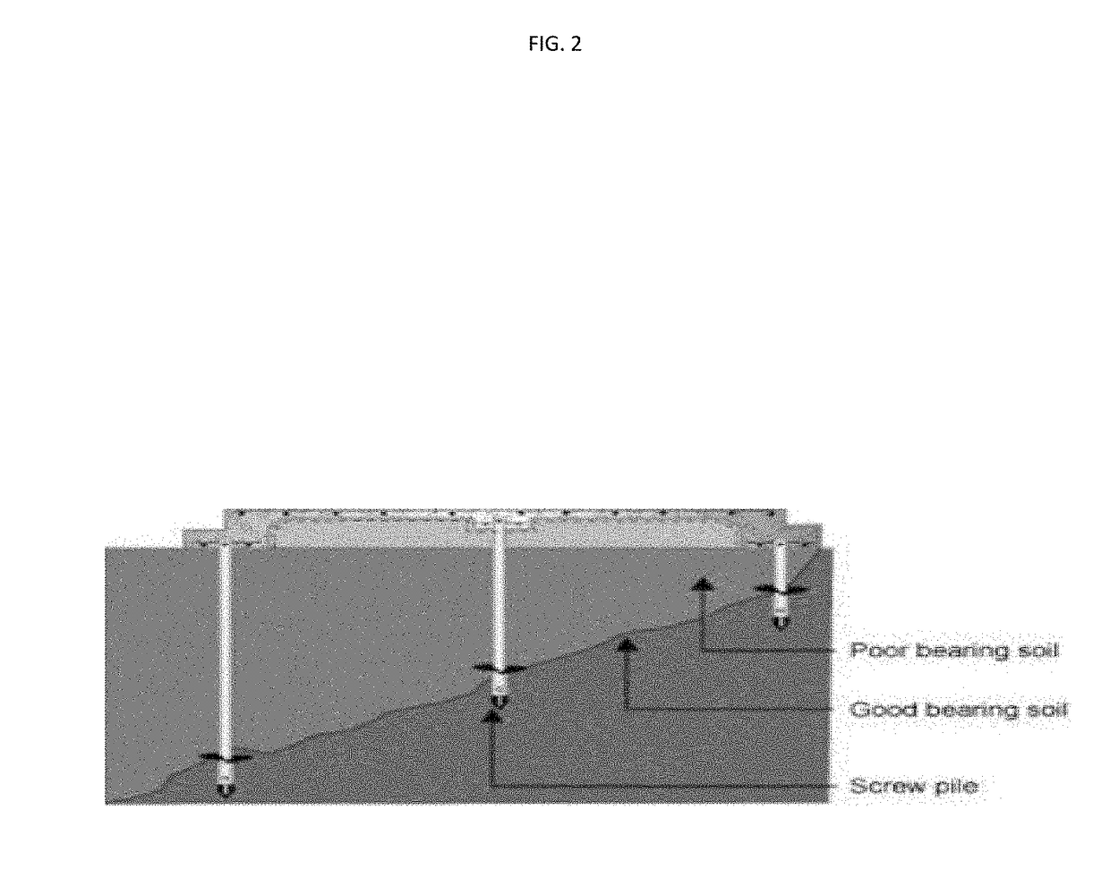
[0009]The present invention is generally directed to a seismic source system and installation and anchoring method which uses at least one seismic source, a screw in piling type ground anchor installed into the earth / ground, and means of coupling the energy from the seismic source to the screw in piling ground anchor.

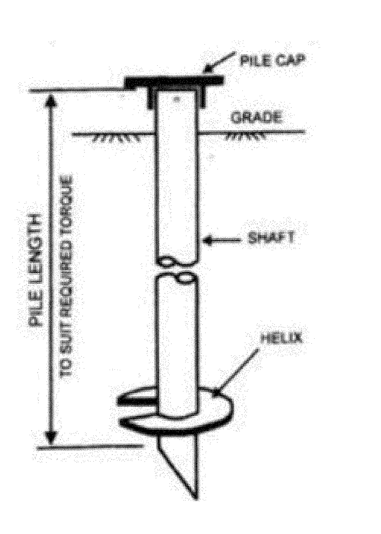
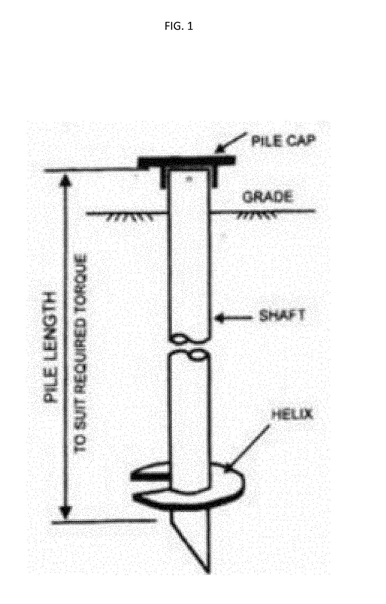
[0010]A typical screw in piling can be anywhere from a few feet long to upwards of 50 feet long. (These pilings are regularly used to install street light poles, foundations, etc., as a more economical means than using cement.) In a preferred embodiment, the top of the screw in piling has a mounting plate that is compatible with mounting a vibratory seismic source. A screw in piling provides excellent mechanical coupling to the earth in both compression and tension which is a must for this application. Cement / concrete pilings are excellent in compression but are typically weak in tension requiring substantial reinforcement. Pounded in pilings rely primarily on friction ...


PUM


Abstract

A seismic source system uses at least one seismic source, a screw in piling ground anchor installed into the earth / ground and means of coupling the energy from the seismic source to the screw in piling ground anchor.

Description

CROSS REFERENCE TO RELATED APPLICATIONS[0001]This application is a non-provisional application which claims priority from U.S. Ser. 62 / 345,281, filed Jun. 3, 2016.FIELD OF THE INVENTION[0002]This invention relates to seismic sources used for determining the structure of the earth's subsurface. Specifically, it provides a simple means of effectively coupling seismic sources to the earth to facilitate maximum transmission of their seismic energy into the earth. It can also be used to couple seismic vibrations from the earth to seismic sensors.BACKGROUND OF THE INVENTION[0003]Seismic sources are used to introduce controlled acoustic waves into the subsurface such that their direct and / or reflected waves can be detected by sensitive sensors at the surface or downhole. The detected energy is typically collected and processed and used to develop images of the subsurface. These subsurface images are regularly used by oilfield companies to locate, monitor, and enhance the recovery from subs...

Claims


Application Information

Patent Timeline
IPC IPC(8): G01V1/047
CPCG01V1/047G01V1/02G01V1/04
Inventor ANDERSEN, JAMES K.
Owner GREENPOWER USA
Why Eureka
Try Eureka