
Tiled display, and display tile and carrier substrate for use in same

a technology for display tiles and carrier substrates, applied in the field of displays, can solve the problems of cumbersome fastening means and support structures, still present challenges, large, thick and heavy, etc., and achieve the effect of substantial variation of pixel pitch and further improvement of the proposed tiled display system

Active Publication Date: 2017-12-07
BARCO NV
View PDF3 Cites 15 Cited by
  • Summary
  • Abstract
  • Description
  • Claims
  • Application Information

AI Technical Summary

Benefits of technology

The patent text describes a new type of display that can be tiled together to create a single large display without any borders or gaps between the tiles. This display is designed to be easy to install and maintain, with minimal discomfort to the user. It can have a flexible design so it can be adjusted to different layouts. Additionally, the distance between the pixels on the display is not affected by the size of the tracks, making it easier to create displays with different numbers of rows and columns. Overall, this invention provides a more efficient and flexible solution for creating large displays without borders or gaps.

Problems solved by technology

They offer solutions to simplify assembly and maintenance of such displays but these solutions still present challenges at the time of assembly and disassembly.
While the solutions proposed in both documents simplify the assembly and servicing of the display element, both the fastening means and the support structure remain cumbersome.
One of the disadvantages of conventional LED display screens is that they are large, thick and heavy.
These conventional LED display screens are made of rigid PCB and can only be mounted on flat surfaces.
The number of cables may make the resulting structure very cumbersome.
To make things worse, thermal expansion can cause the seams to evolve differently across the screen with serious consequences for the visual perception of the displayed image.
For a tiled display, obtaining color and brightness uniformity is often even more difficult, because the tiles and their seams form a regular structure, which is very easily detected by the human eye.
Each strip will also have to be connected to a controller or the strips will have to be daisy-chained with ad-hoc cabling that is likely to be as cumbersome as that of the solutions previously described.
The control of the pixel pitch between two parallel strips can be difficult to guarantee, which means that visual artefacts are likely to affect the display synthesized with the N>1 parallel strips.
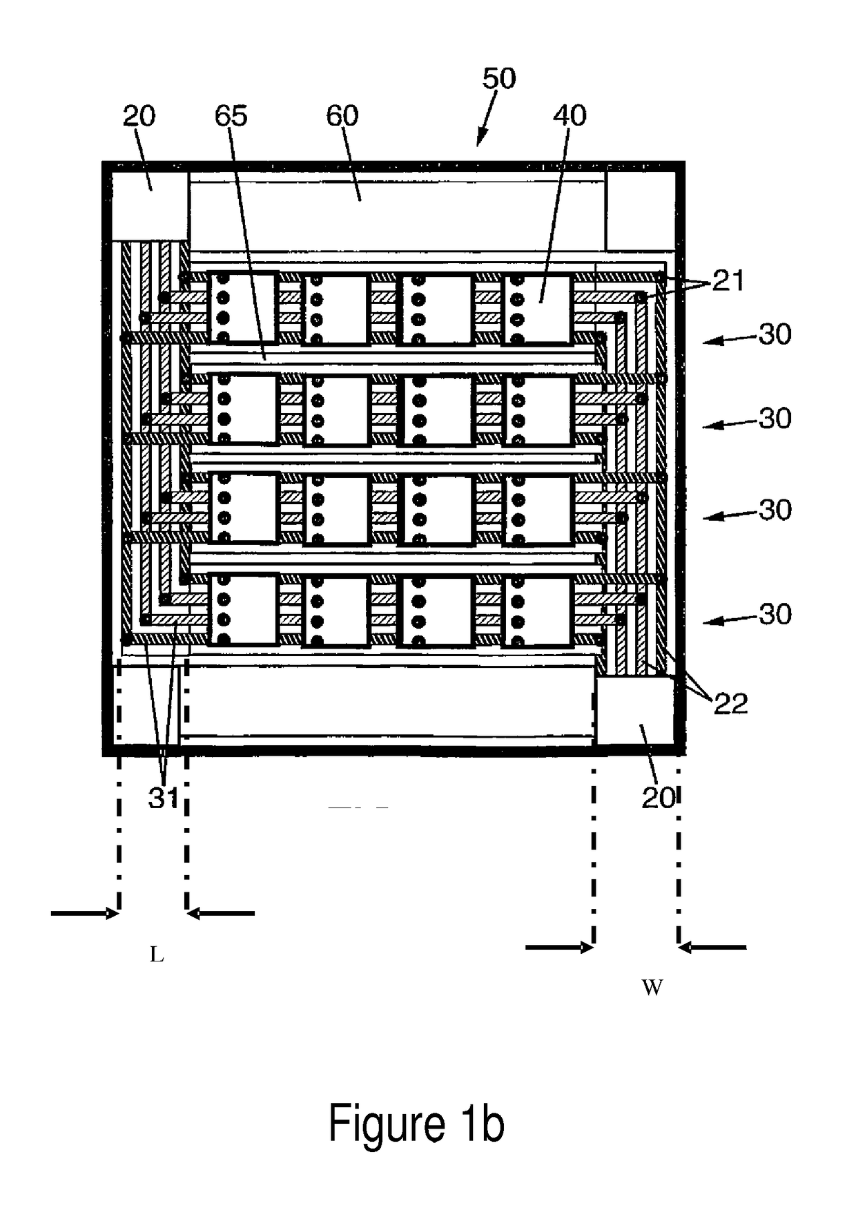
For large displays 50 this may be a problem.
A display with dimensions larger than 5 or 10 m would therefore require the tiling of at least two displays 50 as described in EP 1 716 553 A1, leading to the assembly problems discussed earlier.
There would also be a problem between tiles.
The pixel pitch across the tiled display would therefore not be constant and lead to undesirable visual artifacts.(c) If one LED module is defect, on-site servicing will require the replacement of the entire tile 30 on which the defect LED is located as is usually the case for tiled displays (see e.g. US RE 41,603 E).
For large displays this may lead to reliability issues as current increases linearly with the number of LED on the tile 30.(f) Even if the strips 30 can be made long enough to extend from one end to another of a very large tiled display 50, the substrate 60 still has to be of one piece.
For very large displays, this can be too unpractical and / or costly.
This method does not provide a solution to the problems associated with large modular display systems.
This document is not concerned with flexible display tiles, and it does not disclose using a common substrate carrying multiple display tiles.

Method used


Image

  • Tiled display, and display tile and carrier substrate for use in same
  • Tiled display, and display tile and carrier substrate for use in same
  • Tiled display, and display tile and carrier substrate for use in same

Examples


Embodiment Construction

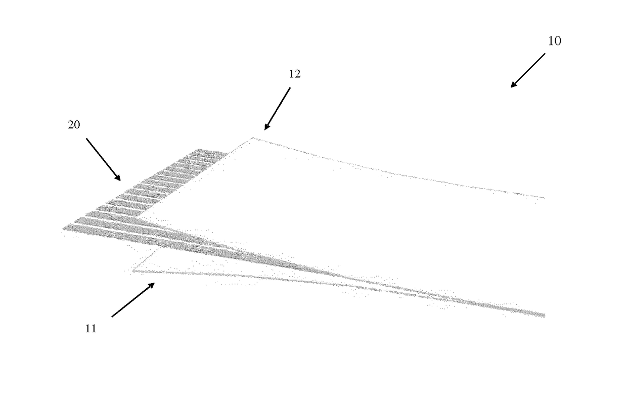
[0071]FIGS. 2a and 2b show a flexible substrate 10 with electrically conducting tracks 20 according to an embodiment of the invention. Each one of the conducting tracks is meant to carry power, data or control signals to LED tiles. For instance, power is conducted through the GND and VSS tracks. The other tracks carry a DATA CLCK signal, DATA (or Video Signal) and COMMAND SIGNAL (the signals considered in e.g. U.S. Pat. No. 7,102,601 to control a tiled LED display; U.S. Pat. No. 7,102,601 is assigned to the present applicant, and its contents, including in particular the description of FIG. 2 therein, are incorporated herein by reference for the purpose of describing the cited signals). The tracks carrying DATA CLCK, DATA and COMMAND SIGNAL may be interrupted at regular intervals as will be discussed in more detail further below.

[0072]In a first preferred embodiment, the conducting tracks 20 are positioned between a first material layer 11 and a second material layer 12. The first a...


PUM


Abstract

A tiled display including discrete luminous sources distributed over at least two adjacent flexible display tiles, each of the flexible display tiles being configured to drive the discrete luminous sources on it when connected to a power supply and when receiving data and control signals. The power, data and control signals are provided to the tiles through conducting tracks formed on a carrier substrate, where an electrical connection between a first conductor on the carrier substrate and a second conductor on a tile is established by using a connecting element having a resilient means keeping it pressed and in contact with a surface of the first conductor or second conductor. Additionally, a carrier substrate and to a flexible display tile for use in such tiled displays.

Description

FIELD OF THE INVENTION[0001]The present invention pertains to the field of displays, in particular to the field of tiled displays and display tiles and carrier substrates for use therein.BACKGROUND[0002]As exemplified by the LED display described in U.S. Pat. No. 5,900,850, typical large tiled display devices require bulky structures to support the display tiles and keep them aligned.[0003]U.S. Pat. No. 8,434,963, assigned to ORBUS, and EP 2 459 888 A1, in the name of the present applicant, give other examples of metallic support structures made of pultruded beams. Both documents describe solutions to problems such as axial and planar alignment of display tiles and illustrate problems such as assembly and disassembly of the support structure and concealment of the support structure.[0004]US 2010 / 0135032 and US 2007 / 0218751, both assigned to Element Labs, Inc., are more particularly concerned by hanging tiled displays. They offer solutions to simplify assembly and maintenance of such...

Claims


Application Information

Patent Timeline
Patent Type & Authority Applications(United States)
IPC IPC(8): G06F3/14H05K1/02G09G3/32
CPCG06F3/1446G09G3/32H05K1/028G09G2330/02G09G2300/026G09G2320/0233G09G2320/0242G09G2380/02H05K3/365H05K2201/10265H05K2201/10106H05K2201/041H05K2201/10318G09F9/3026H01R13/24
Inventor MEERSMAN, KARIMADAMS, GREET
Owner BARCO NV
Learn More