Fluoroscopic Guidance System With Offset Light Source and Method Of Use

a fluoroscopic guidance system and light source technology, applied in the direction of patient positioning for diagnostics, radiation diagnostic clinical applications, applications, etc., can solve the problems of limiting the effectiveness of the positioning device by the clinician, and the possibility of positioning the imaging system

Inactive Publication Date: 2017-12-14
GENERAL ELECTRIC CO
View PDF4 Cites 4 Cited by
  • Summary
  • Abstract
  • Description
  • Claims
  • Application Information

AI Technical Summary

Benefits of technology

[0009]In the exemplary embodiments of the system and associated method, an imaging system utilized to obtain X-ray/fluoro images of the area of interest and the position of the interventional device within the patient includes one or more light sources or emitters, e.g., lasers, positioned on the detector for the imaging system. The lasers are positioned in multiple different offset locations with regard to the detector, such that the lasers are not coaxial with the X-ray beam. This positioning enables each laser to direct a laser beam at a location on the patient within the X-ray beam generated by the imaging system that enables the physician to access the point

Problems solved by technology

However, certain significant issues are present with regard to these prior art systems and methods relates to the laser utilized to illuminate the insertion point on the skin of the patient.
For example, in those systems where the laser is aligned coaxially with the imaging system, i.e., in a bull's-eye view where the laser and the X-ray beam emitted by the imaging system to strike the detector are coaxial, depending upon the position of the body of the patient, the area of interest within the patient, and the desired path of insertion, it may not be possible to position the imaging system at the proper location to enable the laser to illuminate the entry point on the patient.
A further drawback of the coaxial position of the laser and the X-ray beam is that,

Method used


Image

  • Fluoroscopic Guidance System With Offset Light Source and Method Of Use
  • Fluoroscopic Guidance System With Offset Light Source and Method Of Use
  • Fluoroscopic Guidance System With Offset Light Source and Method Of Use

Examples


Embodiment Construction

[0019]In the following detailed description, reference is made to the accompanying drawings that form a part hereof, and in which is shown by way of illustration specific embodiments, which may be practiced. These embodiments are described in sufficient detail to enable those skilled in the art to practice the embodiments, and it is to be understood that other embodiments may be utilized and that logical, mechanical, electrical and other changes may be made without departing from the scope of the embodiments. The following detailed description is, therefore, not to be taken in a limiting sense.

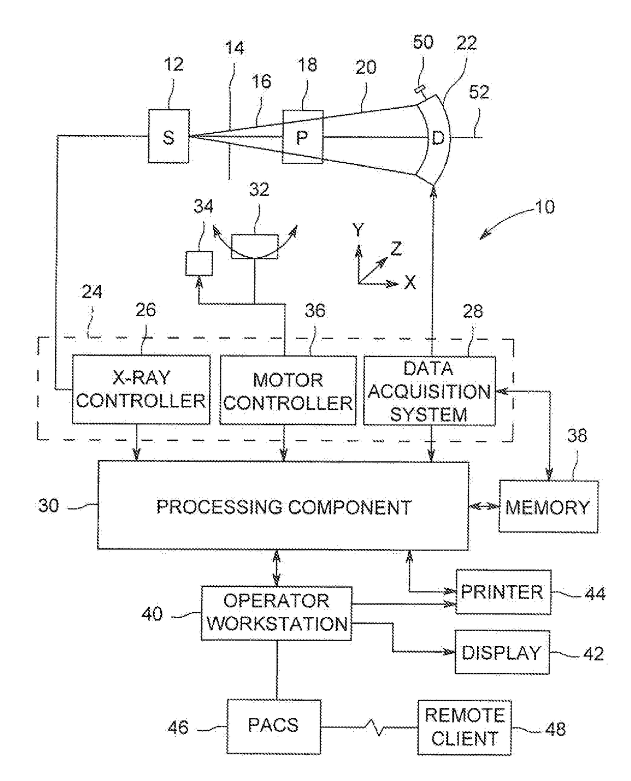
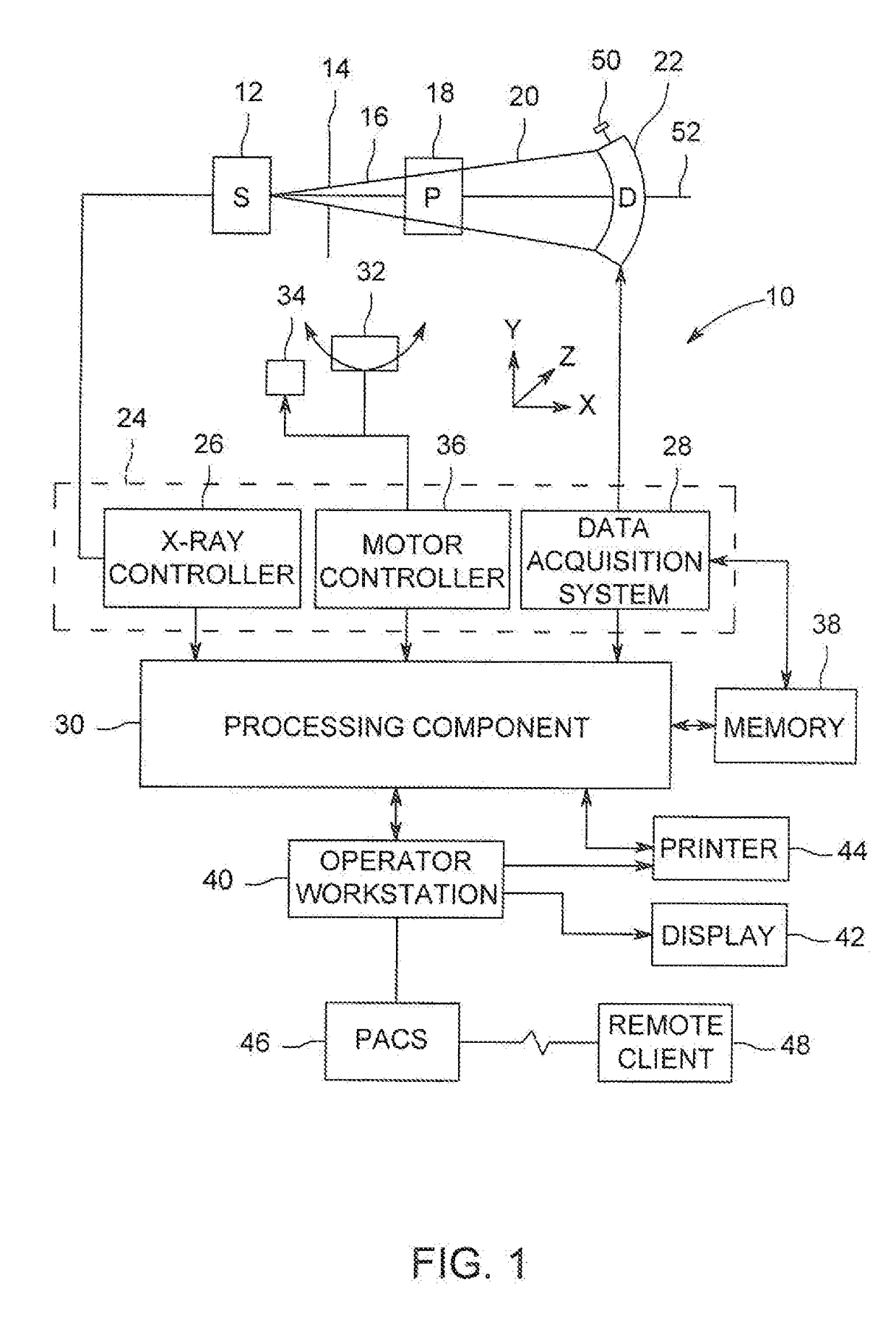
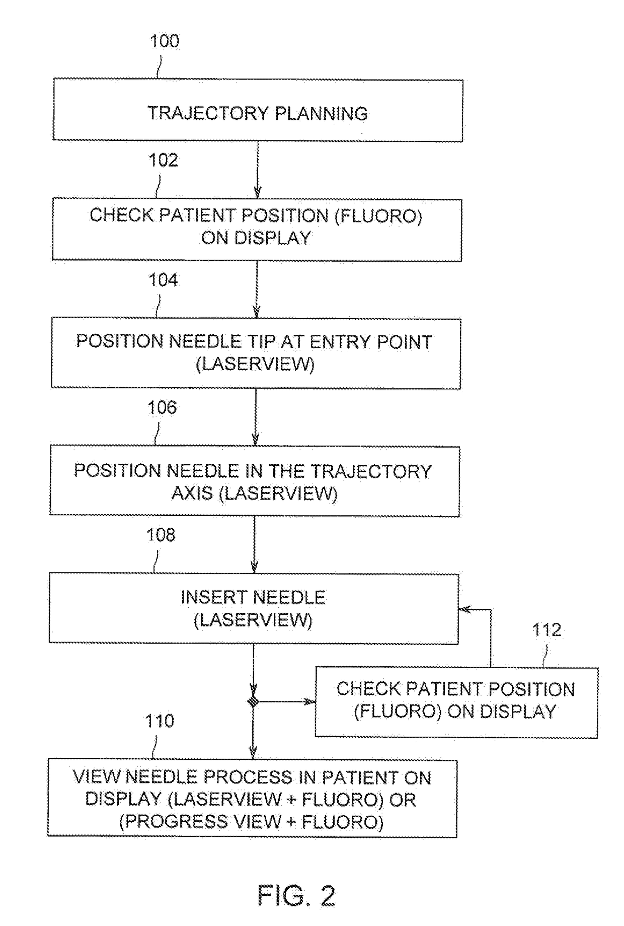
[0020]Exemplary embodiments of the invention disclosed herein relate to a system and method for identifying an optimal trajectory for the insertion of an interventional device into a patient and displaying the position of the device as it is inserted into the body of the patient towards an area of interest.

[0021]The system and method disclosed herein may be suitable for use with a range of ima...


PUM


Abstract

In the present invention, a system and associated method is provided for image-guided navigation during a medical procedure. The system includes a movable gantry having an X-ray source, an X-ray detector and a laser disposed on the detector offset from the area of the detector receiving the beam from the source, a movable table and a system controller operably connected to the gantry, the X-ray source, the X-ray detector, the laser and the table. In the method, the controller determines an optimal trajectory for the insertion of an interventional device into the body to intersect the target, positions the gantry to locate the laser at a point where a laser beam is emitted from the laser along the optimal trajectory outside of the X-ray beam, and takes additional images during the procedure to show the position of the interventional device in the body as compared with the optimal trajectory.

Description

BACKGROUND OF INVENTION[0001]The subject matter disclosed herein relates to the field of image-guided interventional devices and methods, and more specifically to guiding devices and techniques utilized with the interventional devices and methods.[0002]Interventional devices, procedures and methods are used in a variety of situations, such as providing the necessary treatment or diagnostic interaction with the tissue or region of interest within the patient but in a minimally invasive manner, thereby greatly lessening the trauma and recovery time for the patient undergoing the procedure or treatment. As a result, these minimally invasive medical interventional devices, procedures and methods are becoming increasingly important in the treatment of various conditions, including coronary heart disease and are also increasing in the field of biopsies, spinal column treatments and tumor ablations.[0003]In a minimally invasive interventional procedure, one or more medical devices, e.g., a...

Claims


Application Information

Patent Timeline
IPC IPC(8): A61B6/12A61B34/20A61B6/04A61B6/00
CPCA61B6/12A61B6/487A61B34/20A61B6/0407A61B6/4447A61B6/4441A61B6/4085A61B6/461A61B6/4435A61B17/3403A61B90/13A61B2034/107A61B2090/376
Inventor MC CARTHY, THOMAS
Owner GENERAL ELECTRIC CO
Why Eureka
Try Eureka