
Method of manufacturing a catheter sheath

a manufacturing method and catheter technology, applied in the field of catheter sheaths and manufacturing methods, can solve the problems of slow and expensive manufacturing process of catheters, patient risk, and difficulty in using adhesives,

Inactive Publication Date: 2017-12-14
CATHRX LTD
View PDF4 Cites 2 Cited by
  • Summary
  • Abstract
  • Description
  • Claims
  • Application Information

AI Technical Summary

Benefits of technology

The present catheter sheath has a tight seal between the electrode ring and the tubular member, preventing any fluid or substance from passing beneath the electrode ring. This is achieved without using any adhesives and ensures a smooth transition between the electrode ring and the tubular member. The use of the induction heating technique to enhance adhesion between the electrode ring and the tubular member also acts as a preventative measure against the ingress of foreign material and retains the electrodes in position on the catheter sheath, making it more durable.

Problems solved by technology

The problem with mechanical attachment is that it may allow fluid to pass between the ring and the tube.
The use of adhesives may, however, be problematic because particles of the resin may become detached from the catheter tube during use.
This is undesirable as it presents a risk to the patient.
In addition, the application process of the adhesive requires precision and makes the manufacturing process of the catheter slower and more expensive.
These problems are exacerbated for catheters that are reprocessed or reused.
When a catheter tube is cleaned and sterilized after it has been used, the mechanical joint between the ring electrodes and the catheter tube may be weakened and biological matter may enter the catheter tube.
Weakening of the joints and resulting failure can be particularly common after multiple reprocessing cycles.
These cavities may catch biological matter when the catheter is used, and the biological matter may, in turn, be transferred to another patient because these types of small cavities may be difficult to clean.

Method used


Image

  • Method of manufacturing a catheter sheath
  • Method of manufacturing a catheter sheath
  • Method of manufacturing a catheter sheath

Examples


Embodiment Construction

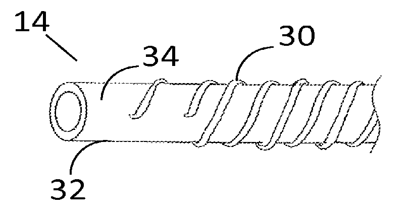
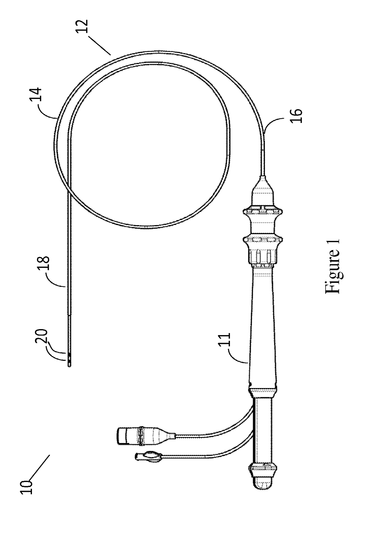
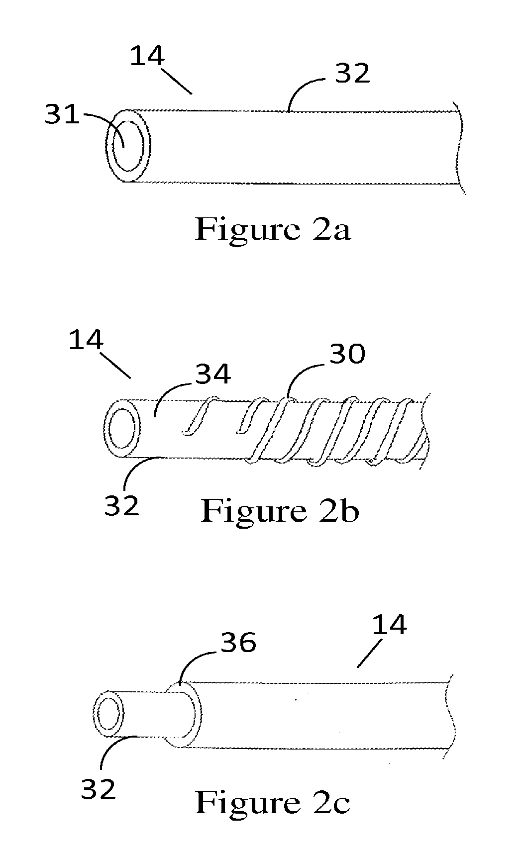
[0028]FIG. 1 depicts a heart catheter 10. The catheter includes a handle 11, and an elongate catheter sheath 12 extending from the handle 11. The catheter sheath 12 consists of a generally tubular member 14 having a proximal end 16 connected to the handle 11 and a distal end 18 having one or more electrodes 20 attached to the tubular member 14.

[0029]The electrodes 20 are in predetermined, axially spaced locations between the proximal end 16 and the distal end 18 of the tubular member 14. Although electrodes of different shapes may be used, an annular electrode ring 20 having an inside diameter equal to or greater than the outside diameter of the tubular member 14 is shown in the accompanying figures. The electrode ring 20 is preferably a platinum-iridium ring but may be made of other suitable conductive material. The inner diameter of each ring approximates the outer diameter of the tubular member 14 so that each ring electrode 20 is a snug fit about an external surface of the tubul...


PUM


Abstract

A catheter sheath comprises a tubular member connected to a catheter handle, the tubular sheath including one or more electrical conductors and one or more electrode rings attached to the tip of the tubular member. The tubular member further includes at least one opening that allows the one or more electrical conductor to be electrically connected to the one or more electrode rings. The electrode ring is slid over the tubular member so as to cover the opening. The tubular member and the electrode ring are subjected to heat treatment by induction heating so that the material of the tubular member melts locally around the electrode ring to form a seal between the tubular member and the electrode ring.

Description

CROSS-REFERENCE TO RELATED APPLICATIONS[0001]This application is a continuation of U.S. application Ser. No. 13 / 816,729, filed Feb. 12, 2013, pending, which is a national phase entry under 35 U.S.C. §371 of International Patent Application PCT / AU2011 / 001010, filed Aug. 12, 2011, designating the United States of America and published in English as International Patent Publication WO 2012 / 019225 A1 on Feb. 16, 2012, which claims the benefit under Article 8 of the Patent Cooperation Treaty and under 35 U.S.C. §119(e) to U.S. Provisional Patent Application Ser. Nos. 61 / 373,725, filed Aug. 13, 2010, and 61 / 409,006, filed Nov. 1, 2010, the disclosure of each of which is hereby incorporated herein by this reference in its entirety.TECHNICAL FIELD[0002]This application relates to a catheter sheath and a method for manufacturing a catheter sheath. In particular, this application relates to a method for attaching an electrode to a catheter sheath of a catheter assembly.BACKGROUND[0003]Any dis...

Claims


Application Information

Patent Timeline
Patent Type & Authority Applications(United States)
IPC IPC(8): A61M25/00A61B18/14
CPCA61M25/0009Y10T29/49117A61M25/0043A61M25/0012A61M25/0015A61B18/1492
Inventor OGLE, DAVIDPARTLETT, MATTHEW J.RYAN, GARRETT
Owner CATHRX LTD
Learn More