Connecting Structure Mounting Wheel To Half Shaft

a technology of connecting structure and half shaft, which is applied in the direction of mechanical equipment, couplings, transportation and packaging, etc., can solve the problems of increased manufacturing process cost, unsafe conditions, and slight movement between the internal spline and the external spline, so as to reduce the locking force of the nut and facilitate assembly and maintenance.

Active Publication Date: 2017-12-14
ZHEJIANG CFMOTO POWER CO LTD
View PDF11 Cites 16 Cited by
  • Summary
  • Abstract
  • Description
  • Claims
  • Application Information

AI Technical Summary

Benefits of technology

[0006]The present invention involves a mounting structure for a wheel of a land vehicle which is mounted on a half shaft. The half shaft has at least one external or internal spline and has a threaded end beyond the spline. The spline has a curvature which differs from a curvature (which can be linear) of the mating arrangement on the wheel mounting bracket, such that longitudinal advancement of the mounting bracket onto the half shaft takes up the clearance between the spline and the mating arrangement and imparts a torsional static binding force between the half shaft and the wheel mounting bracket. A nut threading attaches to the threaded end of the half shaft for securing the wheel mounting bracket to the half shaft. Various road tests of vehicles verify that, when using the present invention, the nut does not loosen during use of the vehicle. The invention enables the locking force of the nut to be reduced, and assembly and maintenance are convenient.

Problems solved by technology

Manufacturing tolerance on the two mating splines are accordingly quite tight and precise, increasing cost to the manufacturing process.
Even with highly accurate manufacturing and tight tolerances, the clearance required for assembly can result in slight movement between the internal spline and the external spline at times of high acceleration or deceleration or when the vehicle is impacted.
Eventually, the loosened locking nut could lead to unsafe conditions.

Method used


Image

  • Connecting Structure Mounting Wheel To Half Shaft
  • Connecting Structure Mounting Wheel To Half Shaft
  • Connecting Structure Mounting Wheel To Half Shaft

Examples


Embodiment Construction

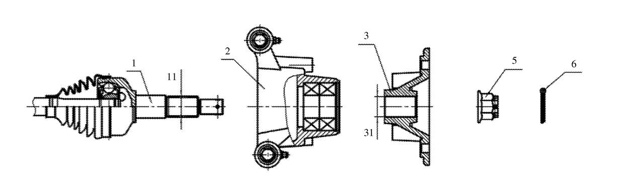
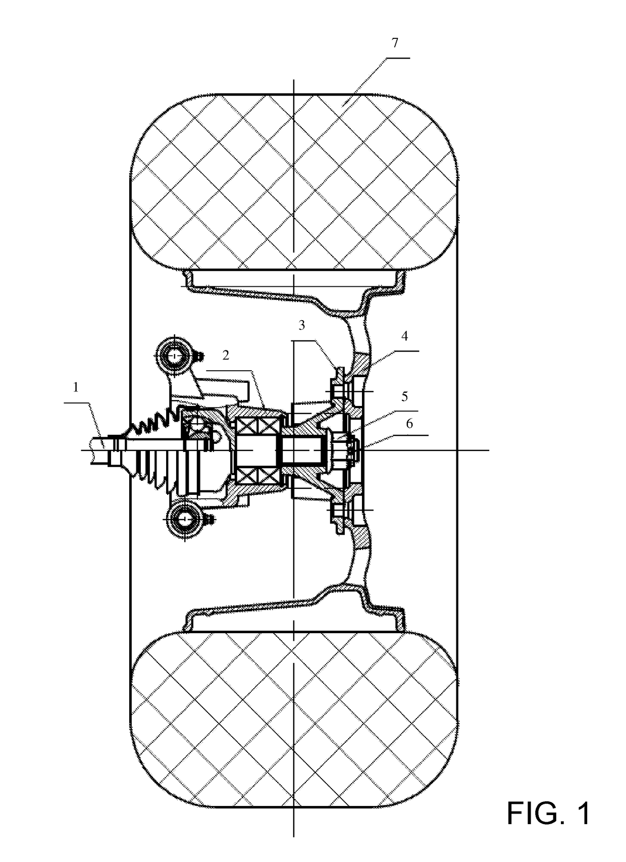
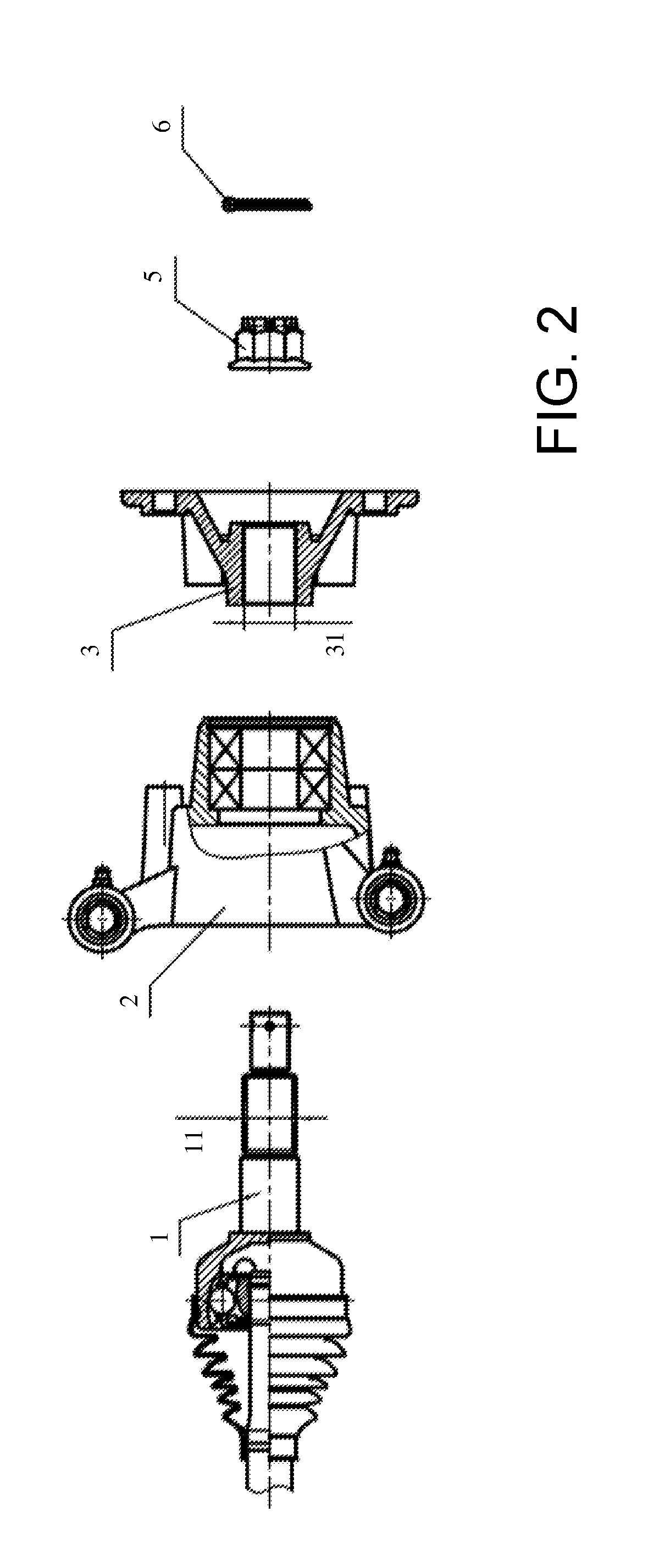
[0025]The present invention is directed at the structure for mounting a wheel of a land vehicle such as an automobile or all-terrain vehicle. As shown in FIG. 1, the wheel has a rim 4 supporting a tire 7 and mounted from a mounting bracket 3 as well known in the art. A half shaft 1 driving the wheel extends through a supporting base 2. Rotation of the half shaft 1 drives the wheel to propel the vehicle, although the invention could alternatively be used with undriven half shafts.

[0026]In the preferred embodiment, the mounting bracket 3 of the wheel is identical to prior art mounting brackets. In this particular example, the mounting bracket 3 includes an internal spline arrangement as known in the prior art. For instance, the internal spline of the mounting bracket 3 may consist of 27 tooth recesses 31 that run longitudinally, i.e., each tooth recess runs parallel to the axis defined by the aperture for the half shaft 1. Moreover, in that FIGS. 1 and 2 do not provide sufficient deta...


PUM


Abstract

A half shaft connects to the mounting bracket of the wheel in a splined connection. The straight external spline of the half shaft is modified to a helical or involute external spline, in which the helix angle adopted is small. The mounting bracket of the wheel can be longitudinally advanced by hand assembly only part way onto the half shaft. The rest of the longitudinal advancement during assembly occurs by tightening the nut to completely eliminate the fit clearance between the external spline and its corresponding mating arrangement. Various road tests of vehicles verify that, when using the present invention, the nut does not loosen during use of the vehicle. The invention enables the locking force of the nut to be reduced, and assembly and maintenance are convenient.

Description

CROSS-REFERENCE TO RELATED U.S. APPLICATION(S)[0001]None.FIELD OF THE INVENTION[0002]The present invention relates to the field of wheeled land vehicles, and particularly to a type of connecting structure mounting the wheel to its half shaft.BACKGROUND OF THE INVENTION[0003]In existing wheeled land vehicles, wheels are supported for rotation by a half shaft which rotates about its axis to provide torque to the wheel. For ease of assembly, repair itself, the wheel typically includes a mounting bracket, and the half shaft is connected to the mounting bracket of the wheel has an internal spline which mates with an external spline on the half shaft. While the mating spline may involve a single longitudinally extending ridge in a corresponding recess, more commonly there are numerous longitudinally extending ridges that mate into corresponding recesses. On the half shaft, the spline is located slightly inward from the end of the half shaft, and the end of the half shaft includes a standa...

Claims


Application Information

Patent Timeline
Patent Type & Authority Applications(United States)
IPC IPC(8): B60B27/06F16D1/10B60B35/14
CPCB60B27/065B60B35/14B60B2320/10F16D2001/103F16D1/10F16D1/108F16D3/223F16D2003/22326B60B27/0026
Inventor CHENG, FUYINGKUANG, ZHENXIANG
Owner ZHEJIANG CFMOTO POWER CO LTD
Why Eureka
Try Eureka