A bellows valve and an injection valve

a bellows valve and injection valve technology, applied in the field of valves, can solve the problems of hydrocarbon reservoir, hydrocarbons not reaching the surface, hydrocarbons not being driven out of the reservoir,

Active Publication Date: 2017-12-14
GASOLINEEUM TECH
View PDF4 Cites 2 Cited by
  • Summary
  • Abstract
  • Description
  • Claims
  • Application Information

AI Technical Summary

Benefits of technology

[0028]The invented bellows valve is robust and reliable, due to its novel bellow-internal valve device and is conveniently usable in combination with an injection valve having

Problems solved by technology

However, there are hydrocarbon reservoirs where the natural flow of hydrocarbons to the surface is not sufficient to allow or maintain profitable production of the well.
This may, for example, be due to the viscosity and / or weight of the hydrocarbons, or that the pressure in the oil well is too low to counter the hydrostatic pressure of the fluid in the well as well as the counter-pressure that the processing installations on the surface exert on the fluid in the oil and / or gas well.
The hydrocarbon reservoir may also, after being in production for some time, lose the pressure that is necessary to drive the hydrocarbons out of the reservoir.

Method used


Image

  • A bellows valve and an injection valve
  • A bellows valve and an injection valve
  • A bellows valve and an injection valve

Examples


Embodiment Construction

[0052]The following description may use terms such as “horizontal”, “vertical”, “lateral”, “back and forth”, “up and down”, “upper”, “lower”, “inner”, “outer”, “forward”, “rear”, etc. These terms generally refer to the views and orientations as shown in the drawings and that are associated with a normal use of the invention. The terms are used for the reader's convenience only and shall not be limiting.

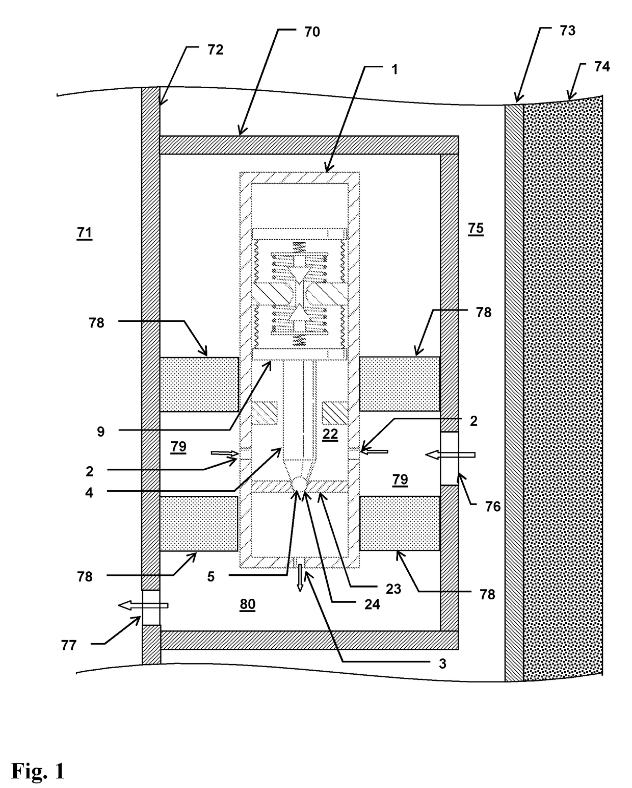
[0053]FIG. 1 illustrates a gas lift valve having a main housing 1, installed in a side pocket mandrel 70. The side pocket mandrel is connected to (or a part of) the outside of a production tubing 71 having a wall 72. The production tubing is positioned inside a casing having a wall 73 towards a subterranean formation 74, whereby an annulus 75 is formed between the casing wall 73 and the production tubing wall 72. These components, their configuration and use, are well known to the skilled person and amply illustrated in the prior art, and need therefore not be described further here. ...


PUM


Abstract

A bellows valve includes a first bellows connected to a first cap member at one end and to a support member at the other end, and a second bellows connected to a second cap member at one end and to said support member at the other end. Respective first and second bellows cavities are thus formed inside each bellows. An orifice is arranged to fluidly interconnect the first and second bellows cavities, and a bellows-internal valve device is arranged to selectively open and close the orifice. The bellows-internal valve device includes first and second resilient members arranged on respective first and second sides of the support member and having respective portions being coupled to respective first and second holding members on the valve device. The bellows valve is useful in injection valves, such as gas lift valves.

Description

FIELD OF THE INVENTION[0001]The invention relates to the field of valves, and more particularly to injection valves. More particularly, the invention concerns a bellows valve and an injection valve, as set out by the preambles of claim 1 and claim 12.BACKGROUND OF THE INVENTION[0002]The use of bellows is well known within the field of mechanical engineering. In that context, bellows are generally elastic vessels that are compressible and expandable when subjected to positive and negative pressures. These bellows are typically made of a suitable metal material and are designed to assume its original shape when the pressures are relieved. Metal bellows are typically made by forming, electroforming or by welding individual metal diaphragms to each other. Welded metal bellows are generally preferred for applications requiring high strength, precision, sensitivity and durability. The materials of welded bellows may be titanium, stainless steel or other high-strength, corrosion resistant,...

Claims


Application Information

Patent Timeline
Patent Type & Authority Applications(United States)
IPC IPC(8): E21B43/12F16K27/02F16K31/122F16K1/12E21B34/10F16K7/02F16K31/126
CPCE21B43/123F16K7/02F16K1/126E21B34/10F16K31/122F16K27/02F16K31/1268F16K41/10F16J3/06
Inventor KLEPPA, ERLING
Owner GASOLINEEUM TECH
Why Eureka
Try Eureka