System for Detection of Foundation Movement in a Wind Turbine

a technology for monitoring system and wind turbine, which is applied in the direction of engine control, motors, engine fuctions, etc., can solve the problems of displacement, part of the foundation member in which the sensors are mounted breaks from the rest of the foundation, and the displacement between the foundation member and the base member exceeds the critical displacement limit, etc., to achieve maintenance free, less prone to environmental impacts, and easy installation

Active Publication Date: 2017-12-14
SCADA INT AS
View PDF2 Cites 5 Cited by
  • Summary
  • Abstract
  • Description
  • Claims
  • Application Information

AI Technical Summary

Benefits of technology

[0033]The subject matter of this application, in its various aspects, provides for a monitoring system, devices, uses and methods which are

Problems solved by technology

It is a significant problem if the load of the foundation is so large that the displacement between a foundation member and a base member attached to the foundation member exceeds a critical displacement limit.
Although the monitoring system disclosed in WO 2013/167128 A1 provides for efficient and precise monitoring of the displacement between the foundation member and the base member of a wind turbine tower, this system nevertheless presents a number of drawbacks.
One drawback is that in a situation in which the sensors are arranged on the inside of the turbine tower, it may happen that a displacement is occurring in such a way that the part of the foundation member in which the sensors are mounted breaks loose from the rest of the foundation.
Installing the monitoring system of WO 2013/167128 A1 on the outside of the turbine tower makes

Method used


Image

  • System for Detection of Foundation Movement in a Wind Turbine
  • System for Detection of Foundation Movement in a Wind Turbine
  • System for Detection of Foundation Movement in a Wind Turbine

Examples


Embodiment Construction

[0041]The First Aspect

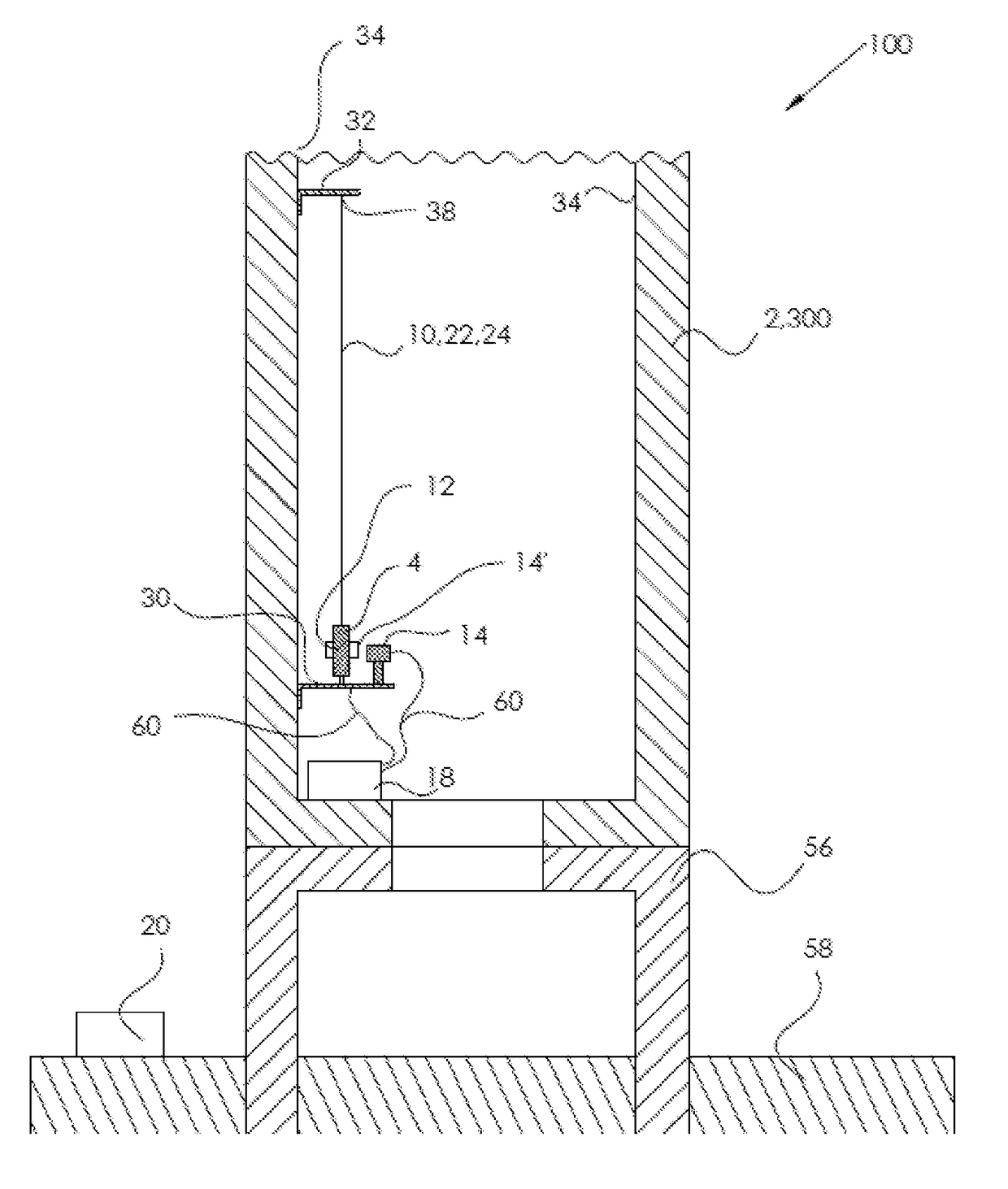
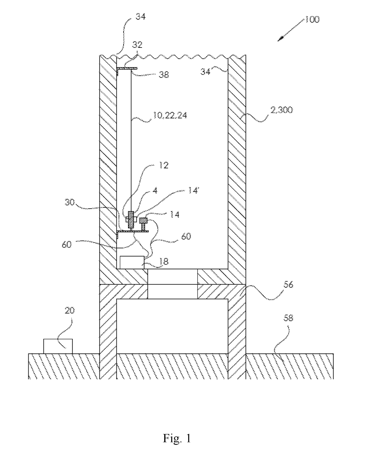
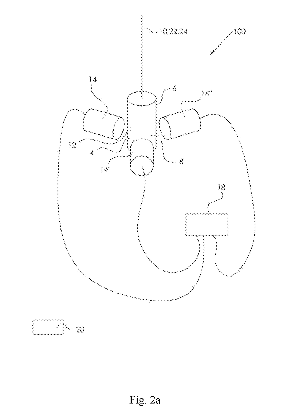
[0042]In its first aspect, the present application relates to a monitoring system for monitoring displacement of a wind turbine tower, in which the monitoring system includes:[0043]one or more plumb bobs each having an upper part and a lower part; each plumb bob being configured to be pivotally suspended at its upper part, via suspension devices, from a point above so as to attain a rest position in a rest situation; each of the plumb bobs including one or more sensing surfaces;[0044]one or more suspension devices for suspending said one or more plumb bobs;[0045]two or more sensors, each being configured to sense, in a specific sensing direction, a distance to a plumb bob, and thereby provide a displacement data;

[0046]wherein at least two of the two or more sensors are arranged in a sensing vicinity of a plumb bob;

[0047]wherein at least two of said specific sensing directions are not parallel to each other;

[0048]wherein the monitoring system further includes a ...


PUM


Abstract

A monitoring system (100) monitors displacement of a wind turbine tower and includes at least one plumb bob with an upper part and a lower part, each plumb bob being configured to be pivotally suspended at its upper part, via a suspension device, from a point above so as to attain a rest position in a rest situation, and each said plumb bob has one or more sensing surfaces (12, 12′). One or more suspension devices means (10) suspend the at least one plumb bob. Two or more sensors (14, 14′, 14″), each being configured to sense, in a specific sensing direction (16, 16′, 16″), a distance to a plumb bob, provide displacement data. At least two of the two or more sensors (14, 14′, 14″) are arranged in a sensing vicinity of a plumb bob, with at least two of the specific sensing directions (16, 16′, 16″) not being parallel to each other. The monitoring system includes a control unit (18) configured to receive the displacement data from two or more of the sensors, and a device for reporting, to an external unit (20), parameter(s) representing displacement of a wind turbine tower.

Description

BACKGROUNDField of Endeavor[0001]The present application relates, in a first aspect, to a monitoring system for monitoring displacement of a wind turbine tower. In a second aspect, the application relates to a device including a system according to the first aspect. In a third aspect, the application relates to a use of a system of the first aspect or the use of a device according to the second aspect for monitoring displacement of a wind turbine tower. In a third aspect, the application relates to a method for monitoring displacement of a wind turbine tower. In a fifth aspect, the application relates to a wind turbine tower including a system according to the first aspect or a device according to the second aspect. In a sixth aspect, the application relates to a wind turbine including a wind turbine tower according to the fifth aspect.Brief Description of the Related Art[0002]Many engineering constructions have a foundation member connecting a tower structure to the ground. One exa...

Claims


Application Information

Patent Timeline
IPC IPC(8): F03D17/00F03D80/80G01B5/14F03D13/20
CPCF03D17/00G01B5/14F03D80/82F03D13/22F05B2240/912F05B2260/83F05B2270/821G01B5/252G01B13/19G01B21/16G01B21/24G01M5/0025G01M5/0041G01M5/0066G01M5/0083Y02E10/728
Inventor LUNDSGAARD, MARLENEBAGGER, THOMAS
Owner SCADA INT AS
Why Eureka
Try Eureka