Wide Angle Steering with Phase Array with Wide-Element Spacing and Lens Array
Active Publication Date: 2017-12-14
CHARLES STARK DRAPER LABORATORY
View PDF2 Cites 12 Cited by
Summary
Abstract
Description
Claims
Application Information
AI Technical Summary
This helps you quickly interpret patents by identifying the three key elements:
Problems solved by technology
Method used
Benefits of technology
Benefits of technology
The invention is a system and method for optical beam steering that combines a lens array system and an array of optical elements to achieve both wide range of steering angles and good angular resolution. The invention solves the problem of requiring a prohibitive number of array elements for a system operating in the optical regime. The coarse beam steering system uses a lens array system and a translation stage to steer the beam between grating lobes, while the fine beam steering system uses a phased array controller to control the relative phase of the optical signals corresponding to the optical elements. The pitch size of the optical elements in the array is greater than a wavelength of operation of the system. The invention provides a reasonably sized array with good angular resolution and a wide range of steering angles.
Problems solved by technology
The power requirements for such an array, would be prohibitive, however, for most applications since the tuning power of a few milliWatts is typically needed for each element.
Additionally, each array element requires components, such as phase shifters, and the size of these components limits the ability to closely place array elements.
Wide element spacings are generally problematic because multiple beams (grating lobes) are created.
Method used
Image
Click on the blue label to locate the original text in one second.
Reading with bidirectional positioning of images and text.
Examples
first embodiment
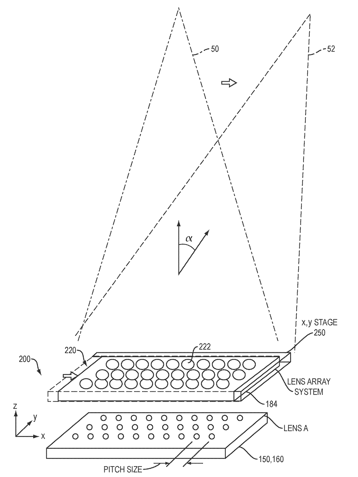
[0051]FIG. 3 shows the coarse steering system 200 according to a This coarse steering system could be used in either the transmitter 102 or receiver 104, or both.
[0052]In this example, the coarse steering signal 184 from the steering controller 180 is provided to a x, y, stage 250 that shifts the lens array 220 in the x, y plane relative to the phased array 150, 160. As shown, this movement of the lens array 220 has the effect of shifting the beam into one of the grating lobes 50, 52. In the illustrated example, the beam is shown being shifted between the primary lobe 50 and the first order grating lobe 52.
[0053]In the illustrated enable, the phased array 150, 160 is shown as a 3 by 10 array. In typical applications, the array will have at least 8 rows and 8 columns. Good performance could be obtained with a 32 by 32 array and 100 rows by 100 columns or more are other options.
[0054]FIGS. 4A and 4B are partial views of the phased array 150, 160 and lens array 220 showing the coarse ...
third embodiment
[0060]FIG. 6 are partial views of the phased array 150, 160 and lens array system 220 showing the coarse beam steering system 220 according to a This embodiment, with its extra lens arrays, better avoids cross illumination.
[0061]Here, a series of lens arrays 230, 240, 236 are used to refocus and coarsely steer.
[0062]Starting with the example of a transmitter, the lenses 232 of the first lens array 230 focus the light from the transmission elements 158 to a set of spots, incident on the lens 242 of the second array 240. The second array 240 diverts the path of the light. A third lens array 236 collimates the light.
[0063]The x, y stage 250 moves the second lens array 240 and the third lens array 236 in unison to steer the beam. The first lens array 230 is stationary relative to the phased array 150.
[0064]In the example of a receiver, the third lens array 236 receives the incoming light. Its lenses 238 focus the light to spots in the lenses 240 of the second lens array 242. The first ...
PUM
Abstract
An optical beamsteering system comprises an array of optical elements for generating or detecting optical signals, a coarse beam steeringsystem for steering a beam between grating lobes, and a fine beam steeringsystem for steering the beam within a grating lobe imposed by the coarse beam steeringsystem. It can be applied the problem of providing an optical phased array system that has both a wide range of steering angles and good angular resolution with a reasonable number of array elements. By moving the lens array or controlling a liquid crystalcell, power is steered into different grating lobes. Adding a phase shifter for controlling the relative phase of the optical signals corresponding to the optical elements enables steering within the selected lobe.
Description
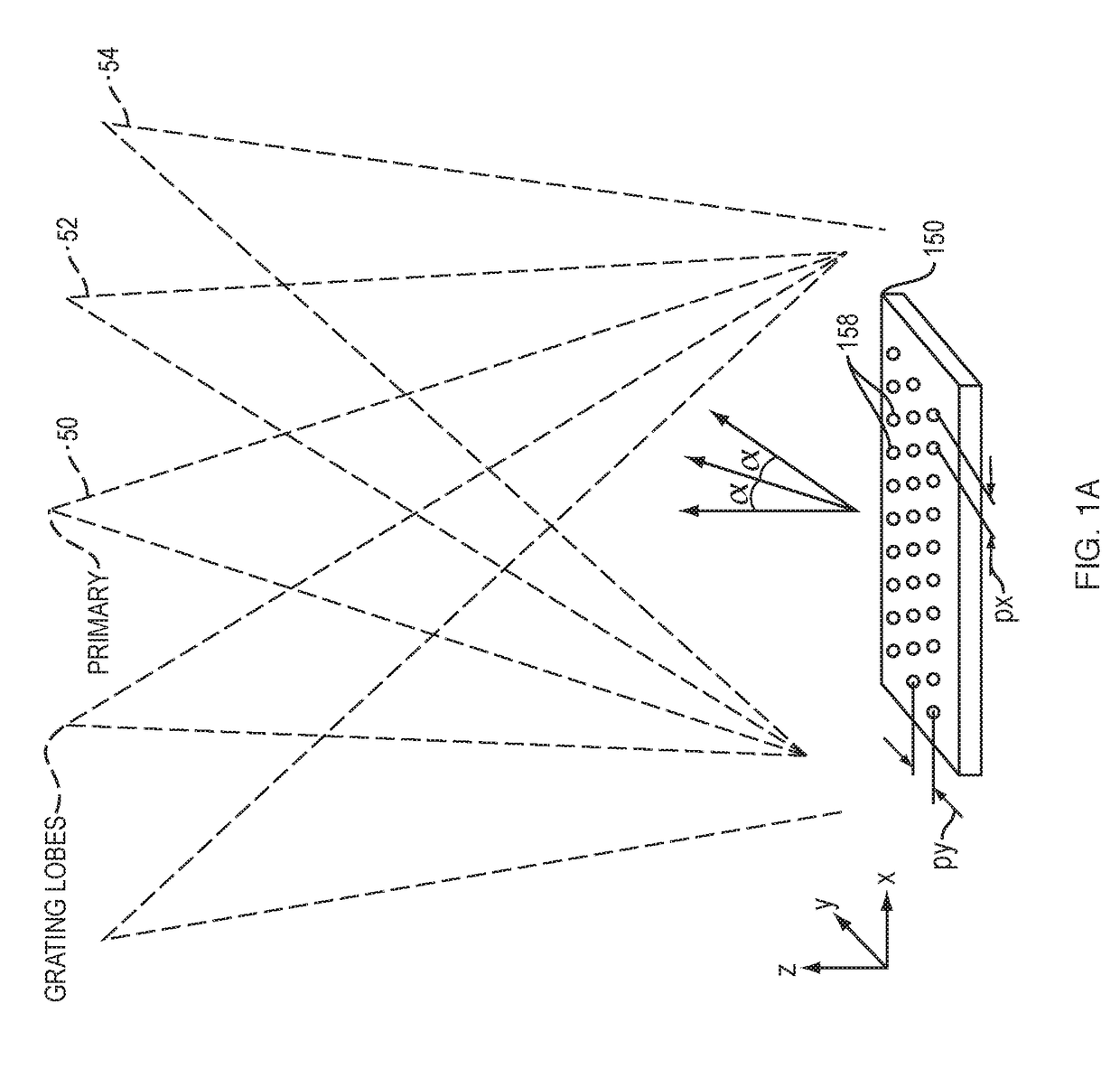
RELATED APPLICATIONS[0001]This application claims the benefit under 35 USC 119(e) of U.S. Provisional Application No. 62 / 349,851, filed on Jun. 14, 2016, which is incorporated herein by reference in its entirety.BACKGROUND OF THE INVENTION[0002]Phased array transmitters are composed of a typically regular two-dimensional array of radiating or transmission elements. Each of these elements typically has an associated phase shifter. Beams are formed by shifting the phase of the signal emitted by each of the radiating elements. The result is constructive and destructive interference in the far field that enable the steering of the beam.[0003]The same principle can be applied to phased array receivers. Similarly, a two-dimensional array of antenna or detection elements receives the incoming radiation. Their corresponding phase shifters shift the relative phase of the signals from each of the detection elements in order to create the constructive interference based on the incoming signal'...
Claims
Application Information
Patent Timeline
Application Date:The date an application was filed.
Publication Date:The date a patent or application was officially published.
First Publication Date:The earliest publication date of a patent with the same application number.
Issue Date:Publication date of the patent grant document.
PCT Entry Date:The Entry date of PCT National Phase.
Estimated Expiry Date:The statutory expiry date of a patent right according to the Patent Law, and it is the longest term of protection that the patent right can achieve without the termination of the patent right due to other reasons(Term extension factor has been taken into account ).
Invalid Date:Actual expiry date is based on effective date or publication date of legal transaction data of invalid patent.

