
Systems, lances, nozzles, and methods for powder injection resulting in reduced agglomeration

a powder injection and powder technology, applied in the field of powder injection systems, can solve the problems of agglomeration breakage, agglomeration breakage, agglomeration breakage, etc., and achieve the effect of reducing agglomeration

Active Publication Date: 2017-12-21
CARBONXT
View PDF3 Cites 0 Cited by
  • Summary
  • Abstract
  • Description
  • Claims
  • Application Information

AI Technical Summary

Benefits of technology

The present invention is about reducing the size of agglomerated particles in a flue gas duct to improve the distribution and contaminant removal of the particles. This is achieved by creating an environment that breaks particle agglomerates and increases the surface area for reaction. The invention includes a lance or nozzle for powder injection that reduces agglomeration and a method for powder injection resulting in reduced agglomeration. The technical effects are improved contaminant removal and increased surface area for reaction.

Problems solved by technology

First, local accelerations induce forces on agglomerates that break the agglomerates apart.
Second, agglomerates break apart when they interact with other agglomerates in the system.
Third, agglomerates break when they interact with a boundary (physical, static, or dynamic).
Fourth, agglomerates break when subjected to gas pressure acting within the agglomerate, which induces sufficient stress in the agglomerate to overcome attractive forces between particles.

Method used


Image

  • Systems, lances, nozzles, and methods for powder injection resulting in reduced agglomeration
  • Systems, lances, nozzles, and methods for powder injection resulting in reduced agglomeration
  • Systems, lances, nozzles, and methods for powder injection resulting in reduced agglomeration

Examples


Embodiment Construction

[0047]While the making and using of various embodiments of the present invention are discussed in detail below, it should be appreciated that the present invention provides many applicable inventive concepts which can be embodied in a wide variety of specific contexts. The specific embodiments discussed herein are merely illustrative of specific ways to make and use the invention, and do not limit the scope of the present invention.

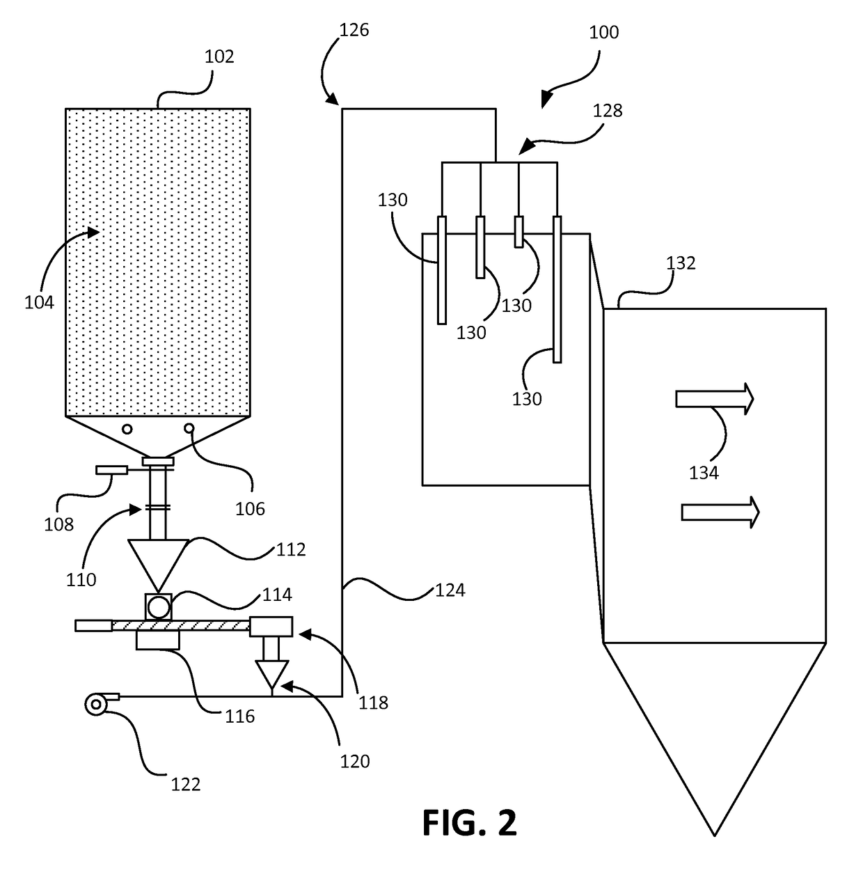
[0048]The various embodiments of the present invention generally relate to a system, lances, nozzles, and / or methods for introducing a powder, such as a powdered activated carbon (“PAC”) and / or activated carbon, into a gas stream with a high degree of dispersion and distribution. In the following description, the term PAC may be used primarily, but the description also applies to activated carbon, and the like as would be commonly known to those skilled in the art. The gas stream and / or process gas stream may originate from many industrial facilities such...


PUM

PropertyMeasurementUnit
circumferenceaaaaaaaaaa
distanceaaaaaaaaaa
radiusaaaaaaaaaa

Abstract

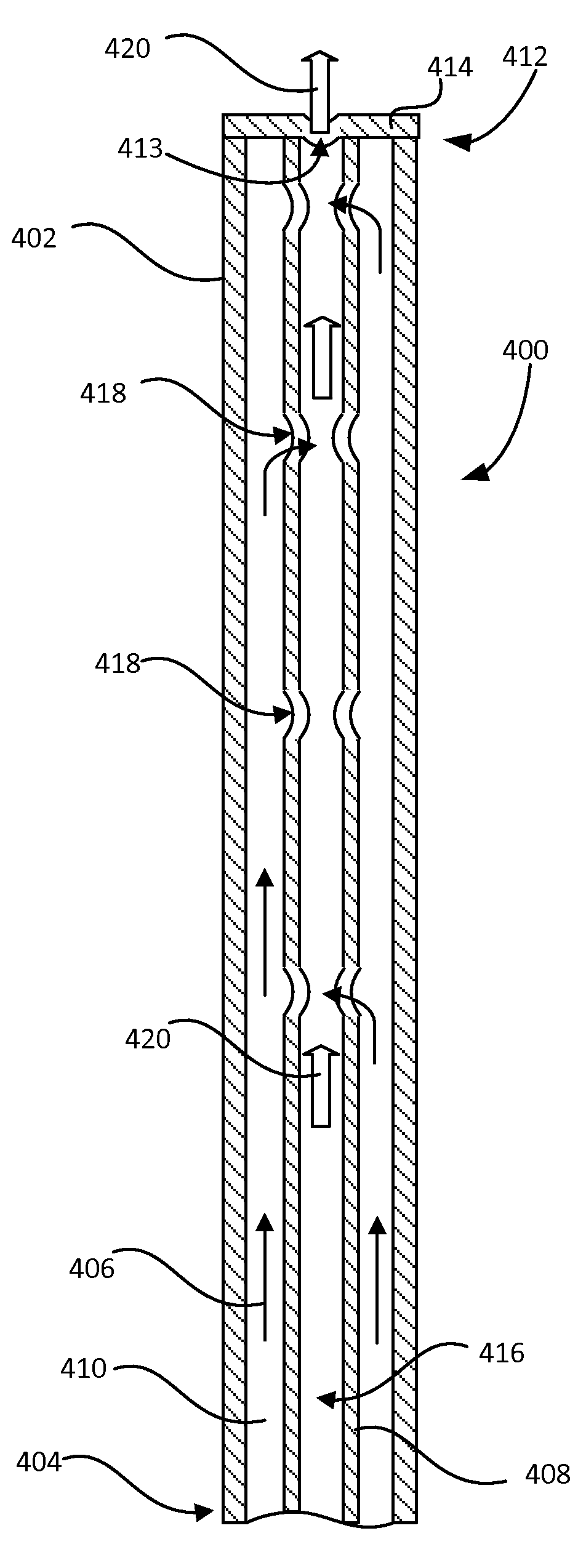
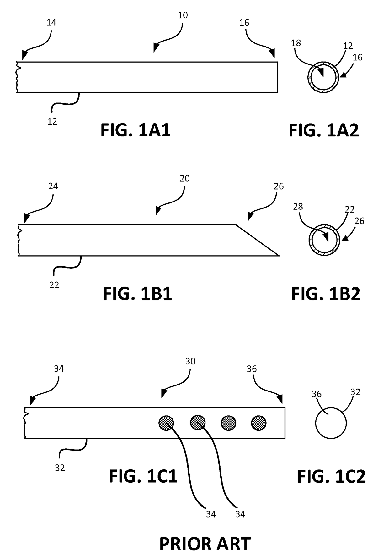
A lance for powder injection resulting in reduced agglomeration, including an outer tubular member having a first end, a second end, and an inner flowpath extending from the first end to the second end; an inner tubular member having a first end, a second end, and a, inner flowpath extending from the first end to the second end, the inner tubular member disposed within the inner flowpath of the outer tubular member for providing an annular space between the outer tubular member and the inner tubular member; and one or more orifices in the inner tubular member for providing a flowpath between the annular space and the inner flowpath of the inner tubular member. Additional lances, systems, and methods are also included.

Description

CROSS-REFERENCE TO RELATED APPLICATIONS[0001]This application claims the benefit of U.S. Provisional Patent Application No. 62 / 019,245, filed Jun. 30, 2014. The entirety of this aforementioned application is incorporated herein by reference.TECHNICAL FIELD OF THE INVENTION[0002]This invention relates, in general, to systems for reducing agglomeration of injected powder and, in particular, to systems, lances, nozzles, and methods for powder injection resulting in reduced agglomeration.BACKGROUND OF THE INVENTION[0003]Without limiting the scope of the present invention, its background will be described in relation to systems for reducing agglomeration of injected powder and, in particular, to systems, lances, nozzles, and methods for powder injection resulting in reduced agglomeration, as an example.[0004]With the introduction of the first national standards for mercury pollution from power plants in 2011, many facilities will turn to activated carbon injection (ACI) to meet the regul...

Claims


Application Information

Patent Timeline
Patent Type & Authority Applications(United States)
IPC IPC(8): B05B1/34B05B7/14B05B1/00
CPCB05B1/34B05B7/14B05B1/005B01D53/10B01D2253/102B01D2257/602B01D2258/0283B01D2259/128F23J15/003F23J2215/60
Inventor MAZYCK, DAVID W.BYRNE, HEATHER
Owner CARBONXT
Learn More