Daylighting device

a daylighting and glass window technology, applied in the field of daylighting devices, can solve problems such as and achieve the effect of suppressing temperature increases and preventing thermal cracking of window glass

Inactive Publication Date: 2017-12-21
SHARP KK
View PDF3 Cites 8 Cited by
  • Summary
  • Abstract
  • Description
  • Claims
  • Application Information

AI Technical Summary

Benefits of technology

[0021]As described in the foregoing, according to one of aspects of the present invention, it is possible to provide a daylighting device capable of preventing thermal cracking of window glass and a substrate in the daylighting device by suppressing temperature increases between the window glass and the daylighting device.

Problems solved by technology

However, if a special daylighting film is attached to a window, there may occur thermal cracking of the window glass.

Method used


Image

  • Daylighting device
  • Daylighting device
  • Daylighting device

Examples


first embodiment

[0079]A daylighting device of the present embodiment is installed, for example, on a part of a window of an office building to guide sunlight into the building's interior.

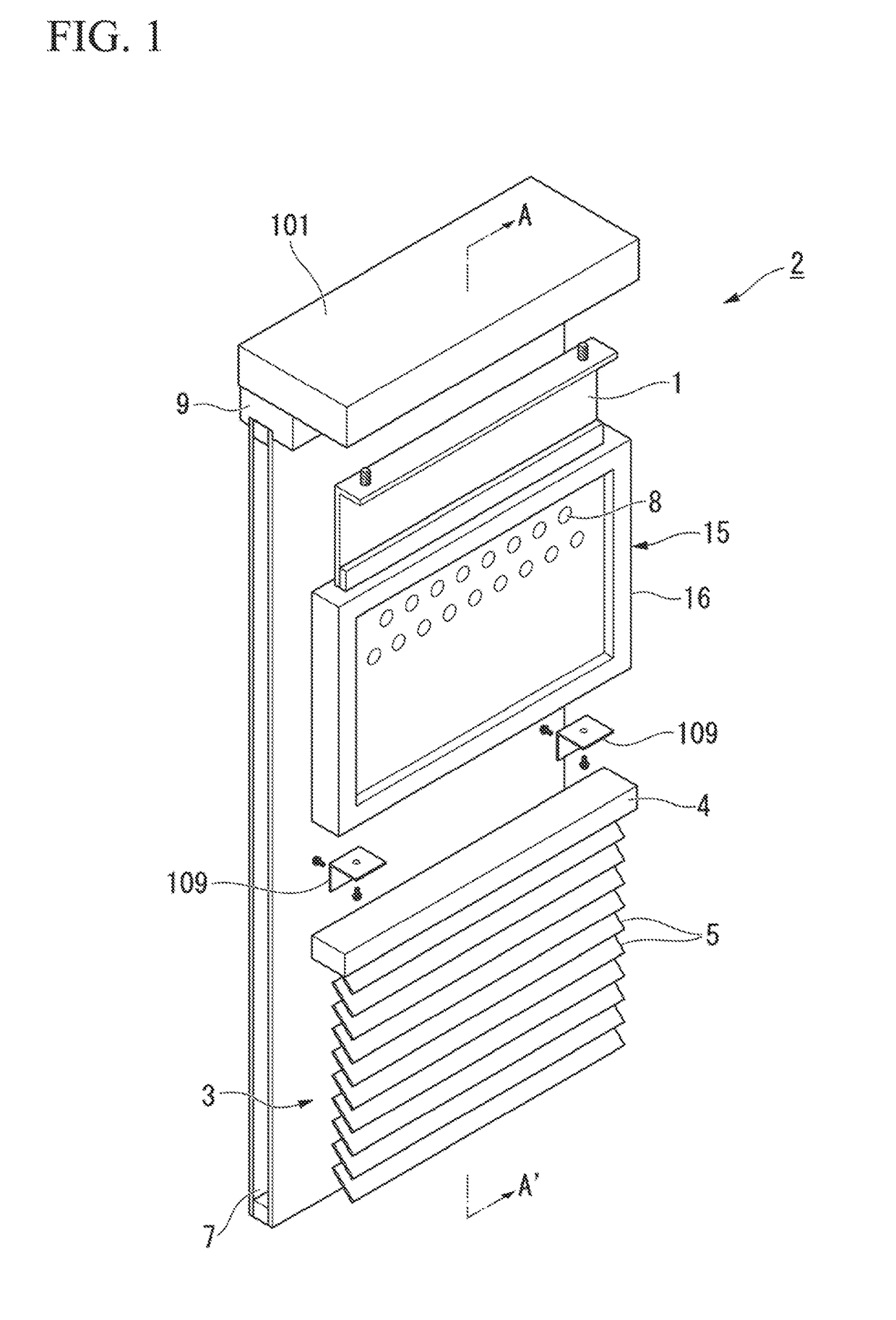
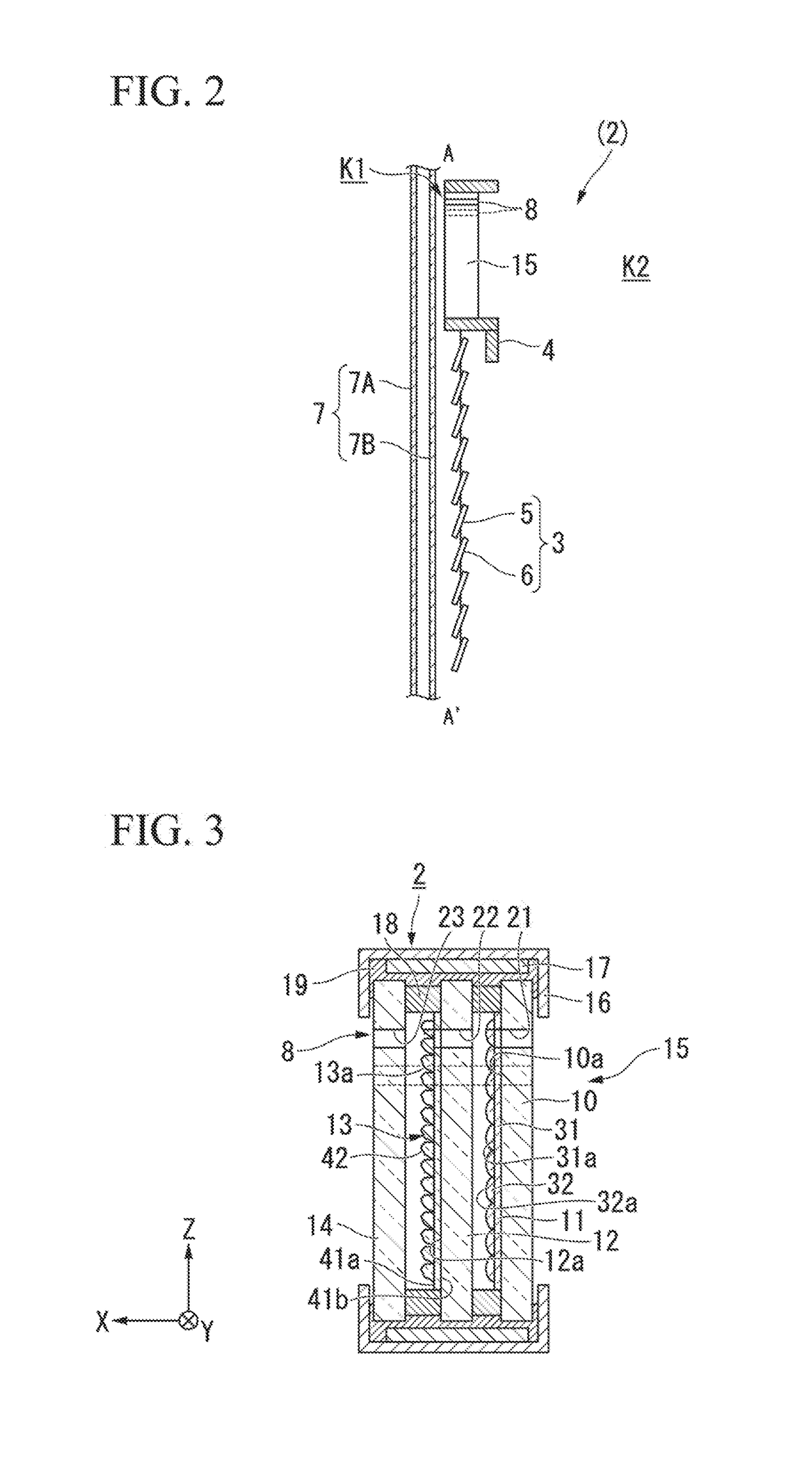
[0080]FIG. 1 is a perspective view of the exterior of a window on which a daylighting device of a first embodiment is installed. FIG. 2 is a cross-sectional view taken along line A-A′ in FIG. 1.

[0081]As shown in FIGS. 1 and 2, a daylighting device 2 is installed on a window frame 101 via an attaching unit 1, and a window shade 3 is disposed on a lower portion of the daylighting device 2. Take, as an example, a typical office room with a window that measures 270 cm in height (from the floor to the ceiling). The daylighting device 2 is located over the range of 70 cm from the ceiling. The window shade 3 covers approximately 200 cm below the daylighting device 2. The window shade 3 is attached to the bottom of the daylighting device 2, for example, via a pair of fixtures 109. The fixtures 109 are omitted in FIG. 2.

[00...

second embodiment

[0182]Next will be described the structure of a daylighting device in accordance with a second embodiment of the present invention.

[0183]FIG. 19 is a schematic cross-sectional view of the structure of the daylighting device of the second embodiment.

[0184]A daylighting device 20 of the present embodiment has a basic structure that is substantially the same as that of the daylighting device of the first embodiment, but differs in that the gaps between glass plates in which through holes are formed are sealed. The following description will elaborate on differences and skip over common features.

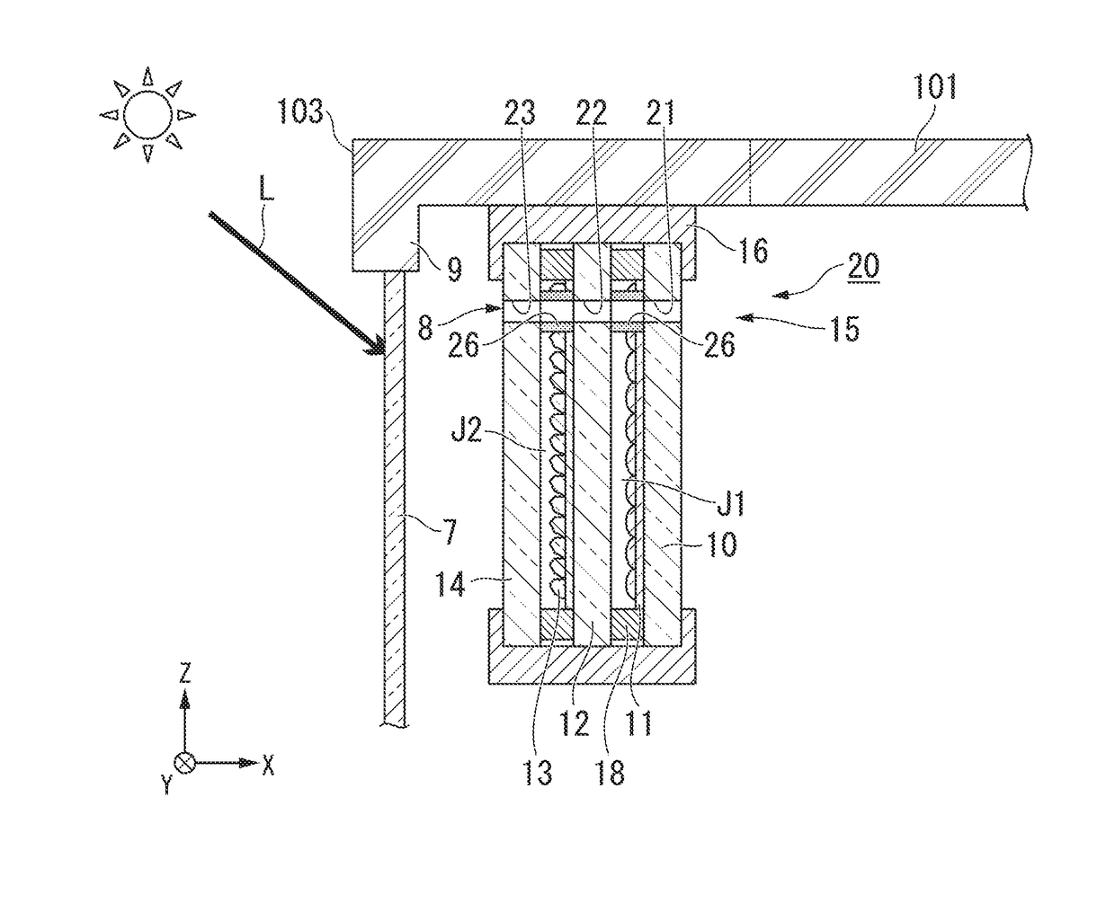
[0185]As shown in FIG. 19, in the daylighting device 20, there are provided sealing members 26, one between the first glass plate 10 and the second glass plate 12 and another between the second glass plate 12 and the third glass plate 14, so as to constitute a part of each ventilation hole 8. The ventilation hole 8 includes a through hole 21 in the first glass plate 10, a through hole 22 in the ...

third embodiment

[0190]Next will be described the structure of a daylighting device in accordance with a third embodiment of the present invention.

[0191]FIG. 20A is a schematic cross-sectional view of the structure of the daylighting device of the third embodiment. FIG. 20A is a cross-sectional view of the daylighting device as viewed from a ceiling end thereof.

[0192]A daylighting device 30 of the present embodiment has a basic structure that is substantially the same as that of the daylighting device of the first embodiment, but differs in that the through hole(s) formed in one / some of the glass plates has / have a different size from the size of the through holes formed in the other glass plates. The following description will elaborate on differences and skip over common features.

[0193]As shown in FIG. 20A, in the daylighting device 30, the through hole 21 in the first glass plate 10 having the light-diffusion sheet 11 thereon is smaller in size than the through holes 22 and 23 formed in other glas...


PUM


Abstract

A daylighting device of the present invention includes: a daylighting member including: a first light-transmitting base member; and a plurality of protruding, light-transmitting daylighting sections provided on a first face or a second face of the first light-transmitting base member; and a ventilation hole configured to enable a space on the first face to communicate with a space on the second face opposite from the first face.

Description

TECHNICAL FIELD[0001]The present invention relates to daylighting devices. The present application claims priority to Japanese Patent Application, Tokugan, No. 2014-245745 filed in Japan on Dec. 4, 2014, the entire contents of which are incorporated herein by reference.BACKGROUND ART[0002]Daylighting films have been proposed for admitting sunlight into a building's interior, for example, through windows of the building. A typical daylighting film includes a light-transmitting support having formed on one of the faces thereof a plurality of unit prisms and a flat face. Sunlight is admitted into the interior through the unit prisms. One can guide external light into the interior to provide a brightly lit space, by attaching such a daylighting film to window glass.[0003]However, if a special daylighting film is attached to a window, there may occur thermal cracking of the window glass. In view of this, Patent Literature 1 describes an insolation adjusting method in which rolling screen...

Claims


Application Information

Patent Timeline
Patent Type & Authority Applications(United States)
IPC IPC(8): E06B3/67E06B7/08E06B7/10F21V31/03F21S11/00E06B7/02
CPCE06B3/67E06B7/08F21V31/03E06B7/10F21S11/007E06B2007/023F21S11/00E06B9/24E06B3/6722E06B7/02E06B2007/026E06B2009/2417E06B2009/2476
Inventor KANNO, TORUKAMADA, TSUYOSHIUEKI, SHUNNISHINAKA, SHUMPEIYUI, HIDEOMISHINOZAK!, DAISUKEUEK!, TOMOKO
Owner SHARP KK
Why Eureka
Try Eureka