Techniques for optimally sensing full containers

a technology of full container and optimal sensing, applied in the field of waste management, can solve problems such as excessive electrical current consumption of sensors

Active Publication Date: 2017-12-21
WASTE HARMONICS LLC
View PDF10 Cites 2 Cited by
  • Summary
  • Abstract
  • Description
  • Claims
  • Application Information

AI Technical Summary

Benefits of technology

[0003]The present invention is a series of techniques incorporated in two sensing methods that enable fullness detection whilst minimizing ...

Problems solved by technology

Sensors that can detect the fullness level are commonplace but...

Method used


Image

  • Techniques for optimally sensing full containers
  • Techniques for optimally sensing full containers
  • Techniques for optimally sensing full containers

Examples


Embodiment Construction

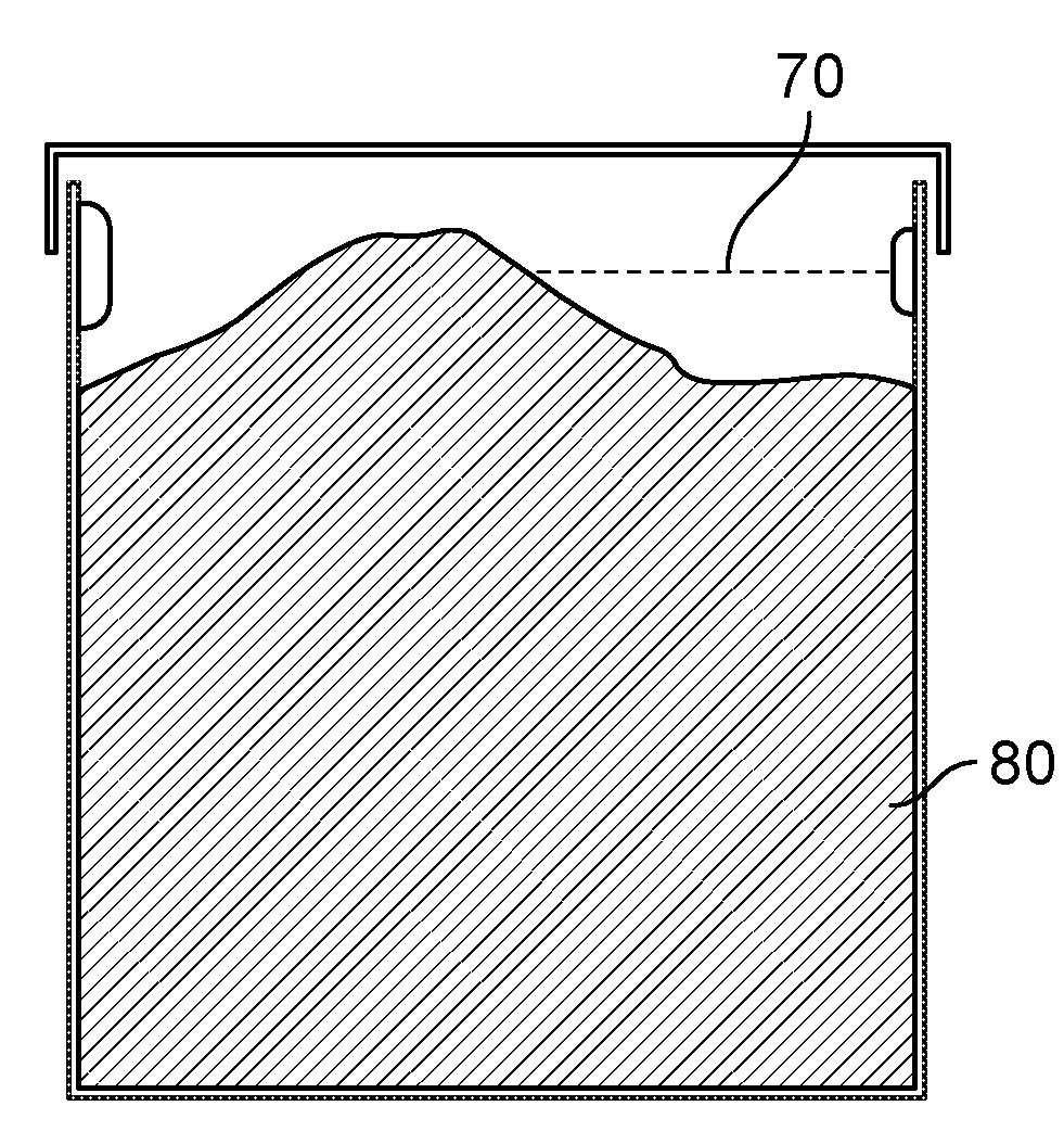
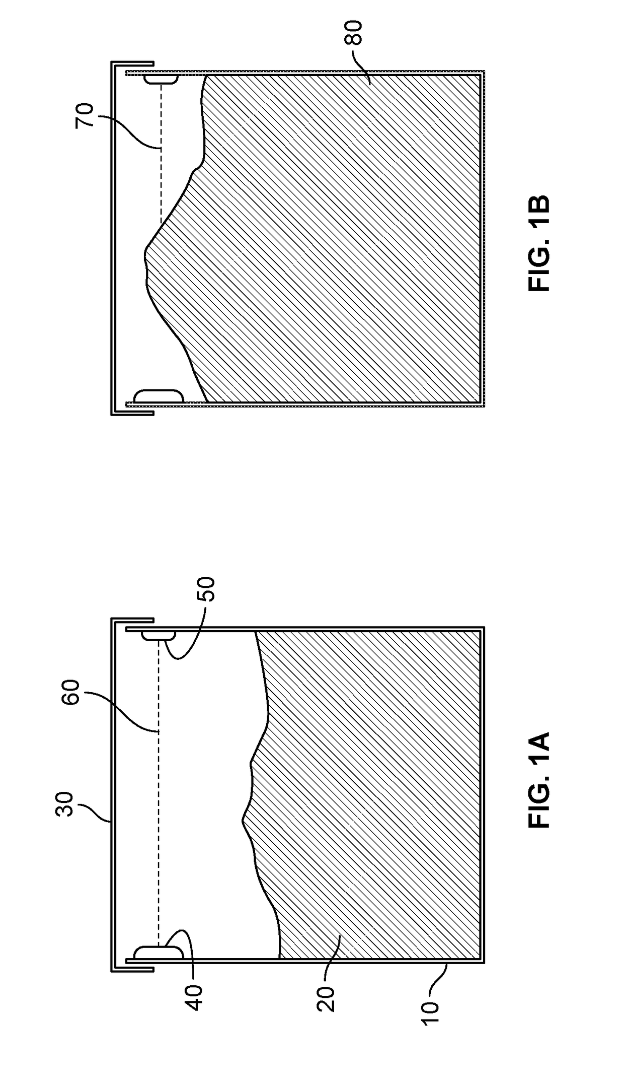
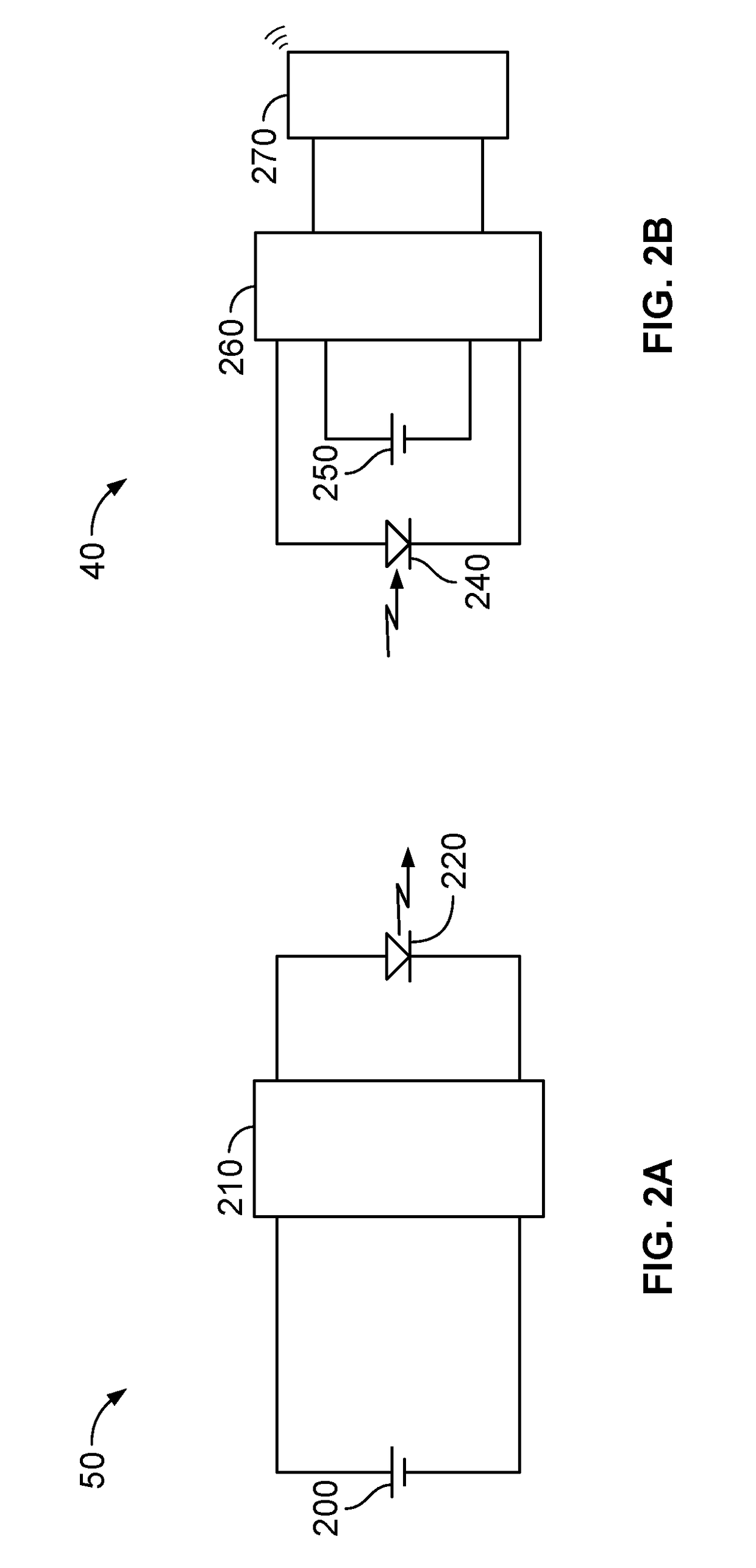
[0009]Referring now to the invention in more detail, in FIG. 1 there is shown a container 10 with substantially vertical side walls and a covering lid 30, and containing a quantum of waste material 20. The container is fitted with a pair of sensor modules, consisting of an Infra-Red Emitter module 50 and an Infra-Red Receiver module 40. The Emitter module emits a pulsed beam of near Infra-Red light modulated with a unique coding pattern according to a pre-defined timing schedule. If the container is not full beyond the limit line set by the linear line 60 connecting the emitter and receiver modules, then the unique coding pattern will be received and recognized by the Receiver module and this can be interpreted as an indication that the container is not full. Conversely, if the container is full 80 beyond the limit line set by the linear line connecting the transmitter and receiver elements, then the beam of near Infra-Red light will be blocked 70 and the unique coding pattern will ...


PUM


Abstract

A series of techniques incorporated in two sensing methods that enable fullness detection whilst minimizing the current consumption of the battery operated wireless electronic circuitry that implements the detection.

Description

BACKGROUND OF THE INVENTION[0001]The present invention is in the technical field of waste management. More particularly, the present invention is in the technical field of sensing the fullness status of containers.[0002]The fullness of containers used in waste management is an important parameter to measure if it is desired to implement an optimal servicing algorithm. Such fullness information is transmitted to a central repository, where software algorithms can then be implemented to allow the generation of optimal routing schedules for the service vehicles. Sensors that can detect the fullness level are commonplace but these sensors suffer from excessive electrical current consumption.SUMMARY OF THE INVENTION[0003]The present invention is a series of techniques incorporated in two sensing methods that enable fullness detection whilst minimizing the current consumption of the battery operated wireless electronic circuitry that implements the detection mechanism and wireless communi...

Claims


Application Information

Patent Timeline
IPC IPC(8): G01V8/12B65F1/16
CPCG01V8/12B65F2210/168B65F2210/1443B65F1/16G05B19/042B65F1/02
Inventor DEVITT, SEAMUSWALSH, BRENDAN
Owner WASTE HARMONICS LLC
Why Eureka
Try Eureka