Method for controlling air control valve

Inactive Publication Date: 2017-12-21
HYUNDAI MOTOR CO LTD
View PDF3 Cites 0 Cited by
  • Summary
  • Abstract
  • Description
  • Claims
  • Application Information

AI Technical Summary

Benefits of technology

[0009]Various aspects of the present invention are directed to providing a method of controlling an A

Problems solved by technology

However, when the ACV is closed to regenerate a DPF, negative pressure is generated in the intake manifold and the combustion chamber.
That is, pressure is generated in the opposite direction to the

Method used


Image

  • Method for controlling air control valve
  • Method for controlling air control valve
  • Method for controlling air control valve

Examples


Embodiment Construction

[0022]Reference will now be made in detail to various embodiments of the present invention(s), examples of which are illustrated in the accompanying drawings and described below. While the invention(s) will be described in conjunction with exemplary embodiments, it will be understood that the present description is not intended to limit the invention(s) to those exemplary embodiments. On the contrary, the invention(s) is / are intended to cover not only the exemplary embodiments, but also various alternatives, modifications, equivalents and other embodiments, which may be included within the spirit and scope of the invention as defined by the appended claims.

[0023]Exemplary embodiments of the present invention will be described hereafter in detail with reference to the accompanying drawings.

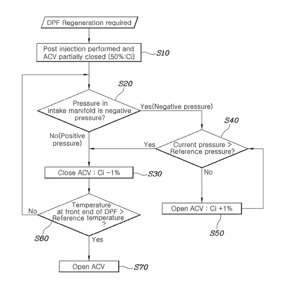
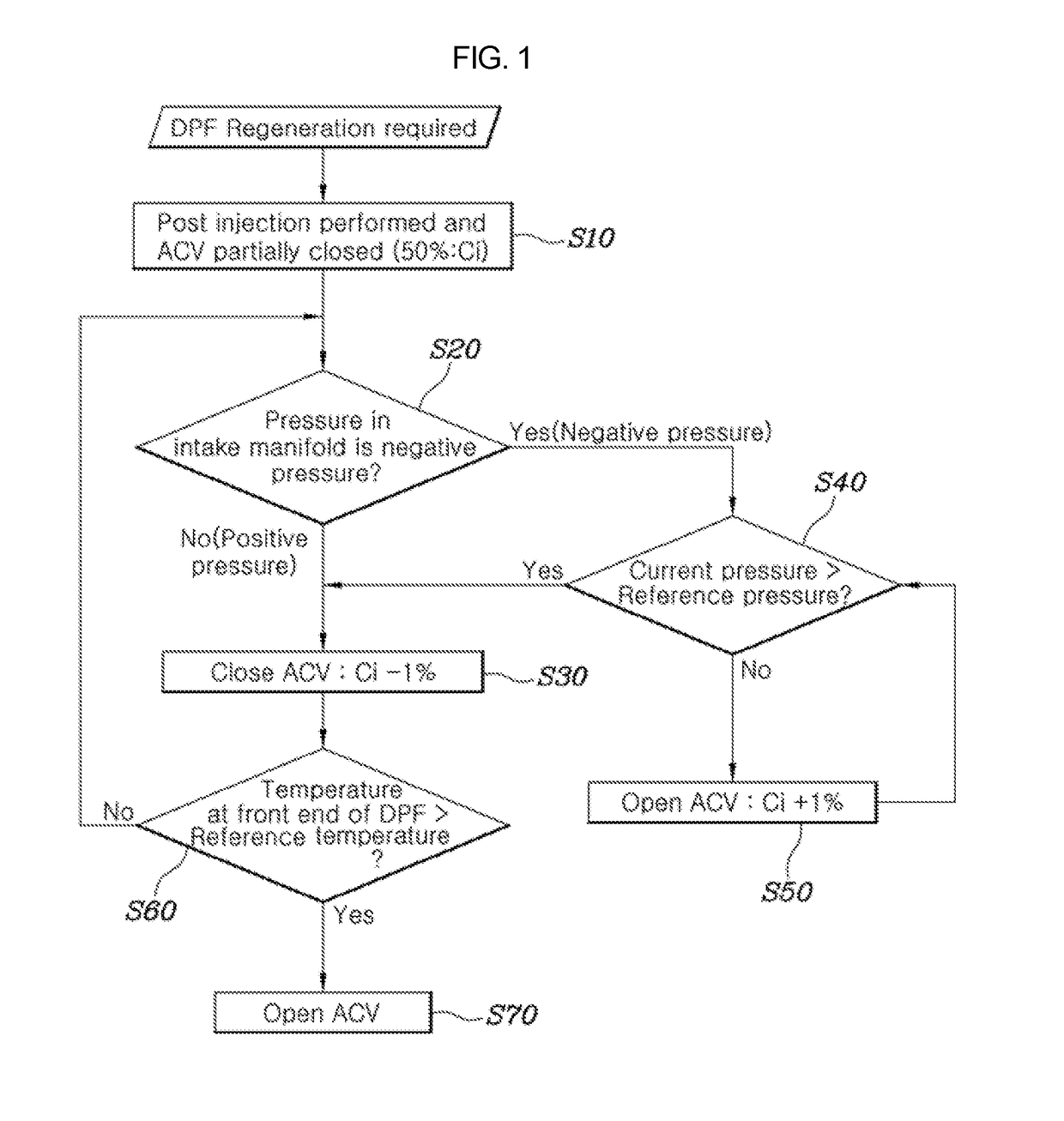
[0024]A method of controlling an ACV of the present invention may include a closing step and an adjusting step.

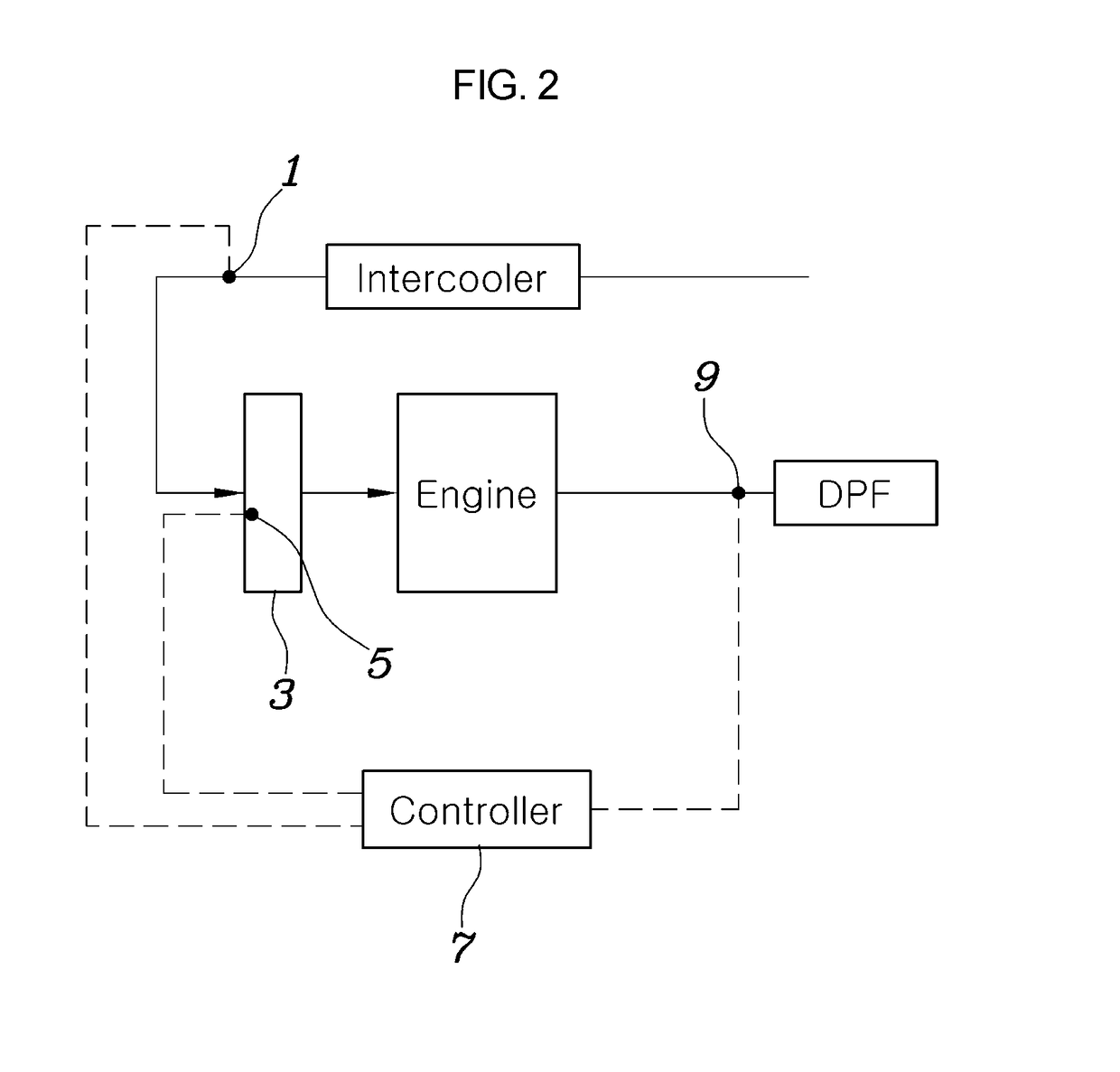
[0025]Referring to FIGS. 1 and 2, in detail, the ACV (Air Control Valve) can be contro...


PUM


Abstract

A method of controlling an ACV to increase a rate of temperature increase of exhaust gas and prevent excessive oil consumption may include a closing step of closing the ACV using a controller when regeneration of an exhaust gas after-treatment device is required, and an adjusting step of opening or closing the ACV using the controller in accordance with whether the pressure in an intake manifold is positive pressure or negative pressure.

Description

CROSS REFERENCE TO RELATED APPLICATION[0001]The present application claims priority to Korean Patent Application No. 10-2016-0076780, filed Jun. 20, 2016, the entire contents of which is incorporated herein for all purposes by this reference.BACKGROUND OF THE INVENTIONField of the Invention[0002]The present invention relates to a method for controlling an ACV (Air Control Valve) to increase a rate of temperature increase of exhaust gas and prevent excessive oil consumption.Description of Related Art[0003]The temperature of exhaust gas should reach a predetermined level for DPF regeneration, and thus it is required to reduce the amount of newly inflowing air in order to quickly increase the temperature of the exhaust gas.[0004]When the fuel-air ratio is increased by closing an ACV to minimize the amount of new air that flows in, the temperature of exhaust gas can be rapidly increased due to the increase in the amount of burned fuel.[0005]Such an ACV (Air Control Valve) is open while ...

Claims


Application Information

Patent Timeline
IPC IPC(8): G05D7/06F01N3/021F01N9/00
CPCG05D7/0635F01N2900/1602F01N3/021F01N9/002F01N3/023F02D41/0002F02M35/10255F02M35/1038F02D2200/0406F02D2200/0802F01N2430/06G05D16/2013Y02T10/40F02D9/02F02D41/0052F02D41/0055F02D2009/0228
Inventor KIM, JONG GULEE, SUNG HAK
Owner HYUNDAI MOTOR CO LTD
Why Eureka
Try Eureka