Regulating transformer rectifier unit for DC power applications

a transformer rectifier and transformer technology, applied in the direction of electric variable regulation, process and machine control, instruments, etc., can solve the problems of ineffective rejection of transient voltage, lack of good regulation of traditional tru units, and multiple drawbacks of traditional tru and r-tru units

Active Publication Date: 2017-12-21
ASTRONICS ADVANCED ELECTRONICS SYST
View PDF4 Cites 17 Cited by
  • Summary
  • Abstract
  • Description
  • Claims
  • Application Information

AI Technical Summary

Problems solved by technology

However, these types of traditional TRU units lack good regulation, and are not effective at rejecting transient voltages that may appear at their inputs.
However, traditional TRU and R-TRU units suffer from multiple drawbacks.
For example, they require a relatively large 400 Hz line frequency transformer that, in an aircraft environment, takes up valuable space and increases weight.
They also exhibit relatively poor energy conversion efficiency due to the high voltage drop that occurs in their output rectifiers.
For example, prior art R-TRU designs typically do not provide more than approximately 85% efficiency.
For example, an over-voltage at the DC output has the potential of creating a hazardous condition on the aircraft, by either damaging critical downstream load equipment so that the equipment no longer functions, damaging redundant equipment due to an over-voltage condition that crosses between redundant power busses, or causing smoke and fire due to damage to equipment that can lead to failure of critical aircraft systems.
In a worst case scenario, such damage can result in catastrophic failure of the aircraft itself.
Traditional R-TRUs may be subject to various failure modes that can cause a dangerous over-voltage condition.
Prior art systems incorporating traditional R-TRUs therefore must include auxiliary safety circuits that prevent over-voltage, leading to additional expense and size of such systems.

Method used


Image

  • Regulating transformer rectifier unit for DC power applications
  • Regulating transformer rectifier unit for DC power applications
  • Regulating transformer rectifier unit for DC power applications

Examples


Embodiment Construction

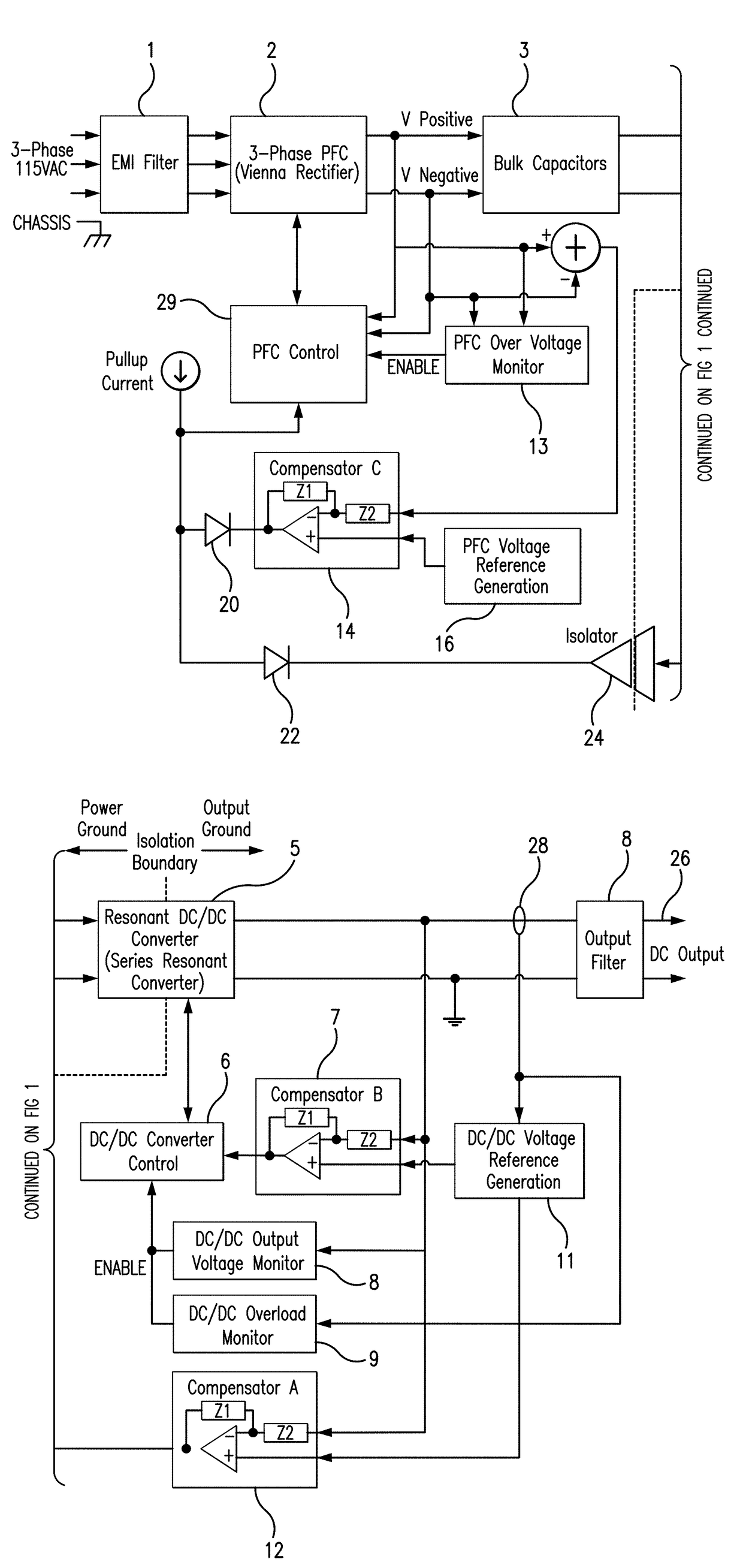
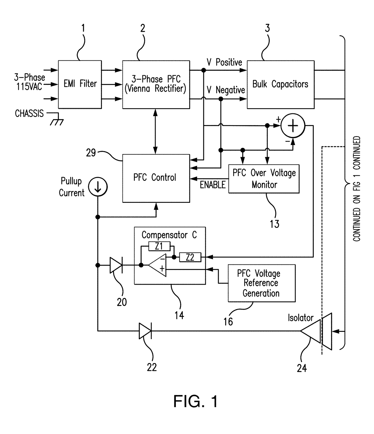
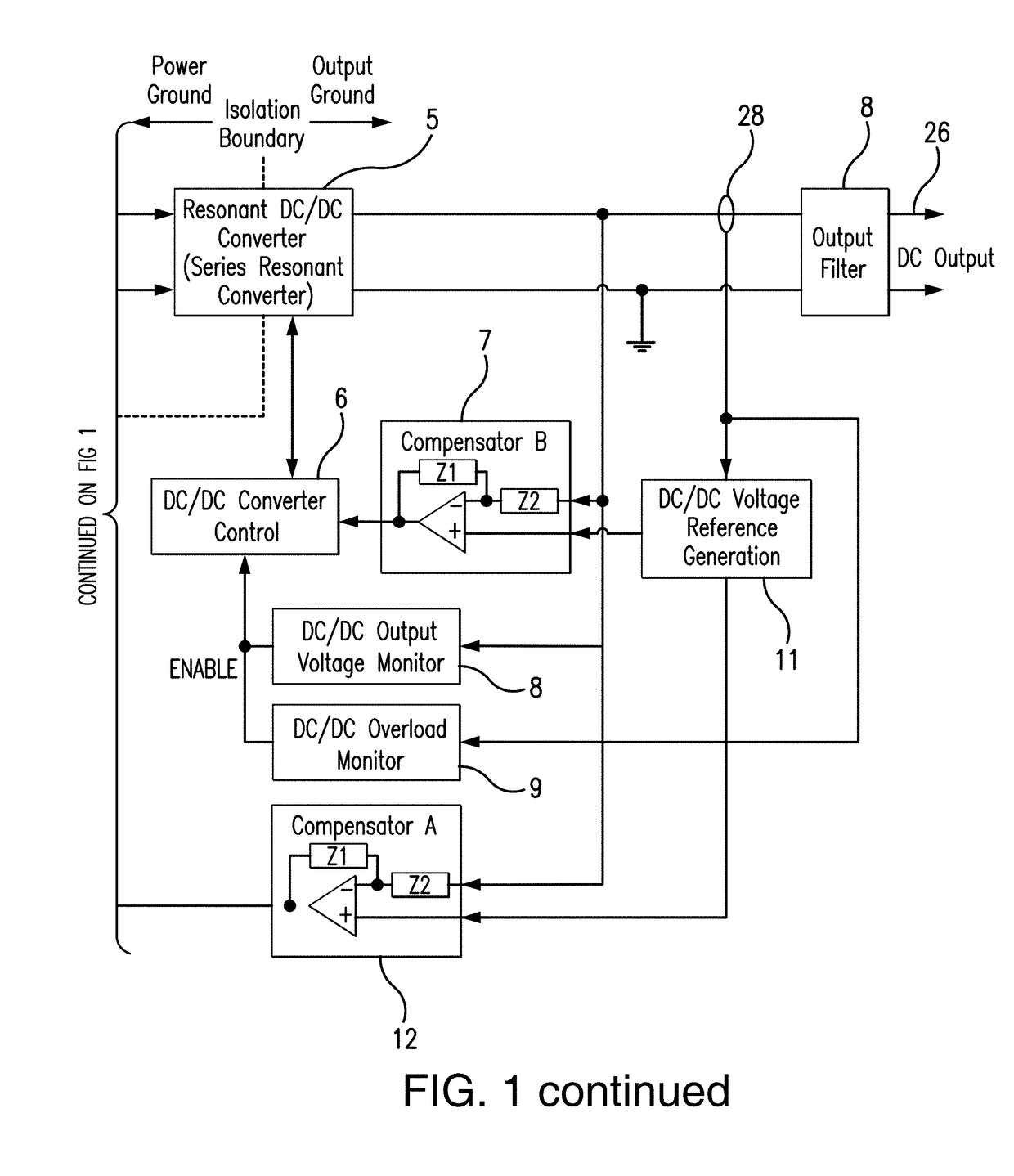
[0020]An exemplary embodiment is described herein with reference to the system block diagram depicted in FIG. 1. As used herein and in the claim language, terms such as “coupled to” or “connected to” shall be broadly interpreted to mean elements that are coupled or connected to other elements either directly or through intervening elements. The more restrictive term “couple directly to” or “connected directly to” will be used to describe couplings or connections that exclude intervening elements.

[0021]Referring to FIG. 1, unregulated three-phase AC power from, for example, an aircraft's generators, is first connected to an EMI (electromagnetic interference) filter 1. As mentioned above, the frequency of the input voltage may vary over a wide range (e.g., 300-800 Hz). EMI filter 1 attenuates RF voltage / currents at the three-phase power input and prevents them from propagating both downstream as well as upstream.

[0022]In the exemplary embodiment of FIG. 1, the EMI-filtered voltage at ...


PUM


Abstract

A power supply system and related method for providing a regulated DC output from an unregulated AC input includes a Vienna rectifier having power factor correction circuitry and a series resonant DC to DC converter to provide a regulated DC output. The power supply system further includes one or more compensator circuits coupled in feedback configuration to control the Vienna rectifier and/or the DC to DC converter and avoid a potentially dangerous over-voltage condition at the regulated DC output.

Description

FIELD OF THE DISCLOSURE[0001]The present disclosure generally relates to power supply systems and methods for providing regulated DC power for various applications from an AC source, including in particular the supply of DC power in an aircraft environment.BACKGROUND OF THE DISCLOSURE[0002]Traditionally, DC power on board aircraft has been derived from three-phase AC power provided by on-board generators, using a Transformer Rectifier Unit (TRU) or an Autotransformer Rectifier Unit (ATRU). Aspects of exemplary prior art systems are described in, for example, U.S. Pat. Nos. 4,866,591, 4,739,446, 6,256,213, 7,796,413, and 8,687,394. The output of the on-board generators, which are driven by the aircraft engines, is typically 115 VAC three phase power at nominally 400 Hz. However, the frequency may vary widely depending on engine conditions (e.g., in the range of 300-800 Hz). The TRU converts this unregulated frequency, three phase voltage into regulated DC power to supply various on b...

Claims


Application Information

Patent Timeline
Patent Type & Authority Applications(United States)
IPC IPC(8): H02M3/335H02M7/04B64D47/00H02M1/36H02M1/08H02M1/42H02M1/44H02M1/00
CPCH02M3/33546H02M1/4241H02M1/44H02M2001/0009H02M7/04H02M1/08B64D47/00H02M1/36H02M1/32H02M1/4216B64D2221/00H02M1/0009H02M1/0058H02M1/007H02M3/33573H02M3/01Y02B70/10
Inventor WAMBSGANSS, WARREN J.
Owner ASTRONICS ADVANCED ELECTRONICS SYST
Why Eureka
Try Eureka