Elastic wave resonator, elastic wave filter, and duplexer
- Summary
- Abstract
- Description
- Claims
- Application Information
AI Technical Summary
Benefits of technology
Problems solved by technology
Method used
Image

Examples
first preferred embodiment
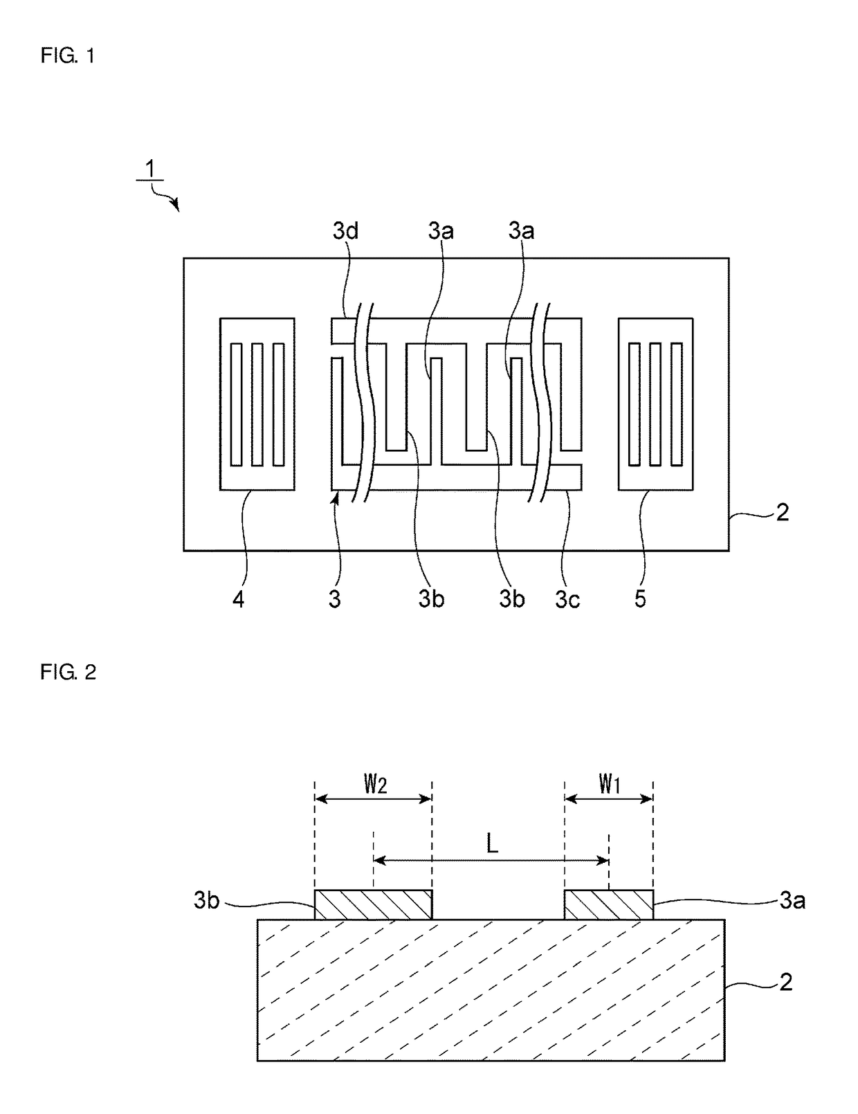
[0025]FIG. 1 is a schematic plan view of an elastic wave resonator according to a first preferred embodiment of the present invention. FIG. 2 is a schematic front-side cross-sectional view illustrating an expanded view of a portion where a first electrode finger and a second electrode finger are arranged adjacent to each other in an elastic wave device according to the first preferred embodiment of the present invention.
[0026]An elastic wave resonator 1 includes a piezoelectric substrate 2. The piezoelectric substrate 2 is a substrate preferably made of LiTaO3, for example. Alternatively, the piezoelectric substrate 2 may be a substrate made of another piezoelectric single crystal, such as LiNbO3 or other suitable piezoelectric material, or may be a substrate made of piezoelectric ceramics, for example.
[0027]As illustrated in FIG. 1, an IDT electrode 3 and reflectors 4 and 5 are provided on the piezoelectric substrate 2, and the reflectors 4 and 5 are respectively arranged at two si...
experimental example
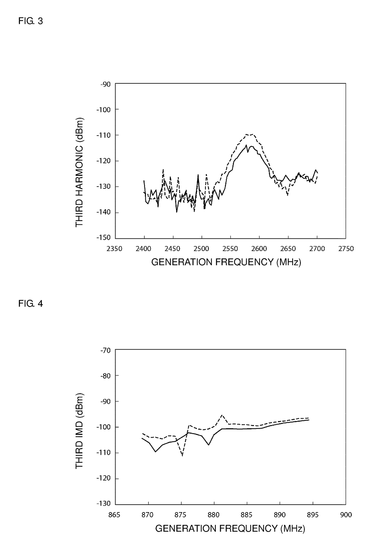
[0039]In the experimental example, one-port type elastic wave resonators 1 were fabricated with the following conditions. In the experimental example, the elastic wave resonators 1 whose resonant frequency in the fundamental mode was about 839 MHz were fabricated.
[0040]Piezoelectric substrate 2: 42° YX-LiTaO3
[0041]IDT electrode 3: Ti / AlCu (layered in the order of Ti and AlCu)
[0042]Number of pairs of electrode finger: 80 pairs
[0043]In the experimental example, samples were fabricated while changing W1 / L and W2 / L, which are the metallization ratio of the first electrode finger 3a and the metallization ratio of the second electrode finger 3b, within the range of about 0.3 to about 0.7, as indicated in Table 1. Specifically, by changing the combination of W1 / L and W2 / L, samples indicated in Table 1, A1 to A8, B1 to B7, C1 to C6, D1 to D5, E1 to E4, F1 to F3, G1 to G2, and H1 were fabricated.
TABLE 1W2 / L0.30.350.40.450.50.550.60.7W1 / L0.3A1A2A3A4A5A6A7A80.35—B1B2B3B4B5B6B70.4——C1C2C3C4C5C...
second preferred embodiment
[0064]FIG. 5 is a schematic plan view of an elastic wave resonator according to a second preferred embodiment of the present invention. As illustrated in FIG. 5, in an elastic wave resonator 21, an adjacent pair of first electrode fingers 3a and 3a and an adjacent pair of second electrode fingers 3b and 3b are alternately arranged along an elastic wave propagation direction.
[0065]A plurality of the first electrode fingers 3a and a plurality of the second electrode fingers 3b, are mutually interposed. The plurality of the first or second electrode fingers 3a, 3b is connected to a first busbar 3c. The plurality of the first or second electrode fingers 3a, 3b is connected to a second busbar 3d.
[0066]In the elastic wave resonator 21, all of the electrode fingers consist of the adjacent pair of first electrode fingers 3a and 3a and the adjacent pair of second electrode fingers 3b and 3b. The adjacent pair of first electrode fingers 3a and 3a and the adjacent pair of second electrode fin...
PUM
 Abstract
Description
Claims
Application Information
 - R&D
- Intellectual Property
- Life Sciences
- Materials
- Tech Scout
- Unparalleled Data Quality
- Higher Quality Content
- 60% Fewer Hallucinations
Browse by: Latest US Patents, China's latest patents, Technical Efficacy Thesaurus, Application Domain, Technology Topic, Popular Technical Reports.
© 2025 PatSnap. All rights reserved.Legal|Privacy policy|Modern Slavery Act Transparency Statement|Sitemap|About US| Contact US: help@patsnap.com