Method of forming a structural portion of a fuel tank for an aircraft

Inactive Publication Date: 2017-12-28
AIRBUS OPERATIONS LTD
View PDF3 Cites 6 Cited by
  • Summary
  • Abstract
  • Description
  • Claims
  • Application Information

AI Technical Summary

Benefits of technology

The patent text is about a new method of making a sensor that does not require a separate dedicated substrate. Instead, the electrodes are embroidered onto a fabric material, which makes them more reliable and accurate. This method also makes the sensor more durable and easy to use. Overall, this makes a better sensor that is more reliable and cost-effective.

Problems solved by technology

The presence of electrical wiring in the fuel tank requires additional precautions and requirements, such as explosion prevention requirements, and also increases manufacturing and maintenance times due to the complexity and difficult accessibility of the interior of the fuel tank.
However, a problem with embedding the sensor in a structural wall of a fuel tank is that stress concentration points may be generated at the periphery of the sensor substrate.
This may reduce the structural integrity and reliability of the fuel tank.

Method used


Image

  • Method of forming a structural portion of a fuel tank for an aircraft
  • Method of forming a structural portion of a fuel tank for an aircraft
  • Method of forming a structural portion of a fuel tank for an aircraft

Examples


Embodiment Construction

)

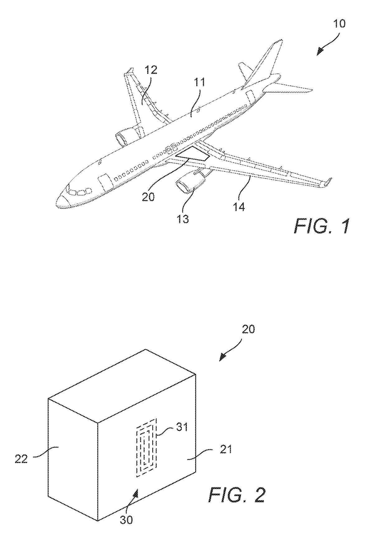
[0041]Referring to FIG. 1, an aircraft 10 is shown. The aircraft 10 has a fuselage 11 and wings 12. The wings 12 extend from the fuselage 11. An engine 13 is mounted to each wing 12.

[0042]Fuel for each engine 13 is stored in one or more aircraft fuel tanks 20. Fuel for each engine is stored in a centre tank within the fuselage 13 and one or more wing tanks within the wings 12. The description below refers to the aircraft fuel tank 20, which could equally refer to the centre tank, any of the wing tanks, or an alternative fuel tank arrangement.

[0043]Referring to FIG. 2, a schematic view of a fuel tank 20 is shown. The fuel tank 20 includes a number of fuel tank structural portion 21, such as a base, outer walls and an upper side. The fuel tank 20 defines a fuel receiving space 22. The fuel tank structural portions 21 may be formed from other structural parts of the aircraft 10, such as skins, ribs and spars. The structural portion 21 is a portion that contributes to the structure of ...


PUM

PropertyMeasurementUnit
Electrical conductivityaaaaaaaaaa

Abstract

The present application relates to a method of forming a structural portion of a fuel tank for an aircraft in which the structural portion is formed from a fibre reinforced polymer and a sensor is integrated in the structural portion. The method includes providing a fibre ply which acts as a structural component, and embroidering an electrically conductive wire in a predetermined pattern on the fibre ply to form the sensor. The fibre ply acts as a sensor substrate. Furthermore, the method includes applying a polymer matrix to the fibre ply so that the fibre ply and electrically conductive wire are covered by the polymer matrix. The present application also relates to a fuel tank for an aircraft, a fuel quantity indicating system, and an aircraft.

Description

FIELD OF THE INVENTION[0001]The present invention relates to a method of forming a structural portion of a fuel tank for an aircraft, in particular a method of forming a structural portion of a fuel tank having a sensor integrated in the structural portion. The present invention also relates to a fuel tank for an aircraft, a fuel quantity indicating system, and an aircraft.BACKGROUND OF THE INVENTION[0002]Aircraft have fuel quantity measuring systems for measuring the quantity of fuel in their fuel tanks. A typical fuel quantity measuring system includes fuel probes in the fuel tank to directly determine the fuel level in the fuel tank.[0003]By placing fuel probes in a fuel tank, the probes are necessarily exposed to fuel in the fuel tank. As such the probes must be capable of long term exposure the fuel environment in the tank. Such an arrangement also requires the provision of electrical wiring in the fuel tank. The presence of electrical wiring in the fuel tank requires additiona...

Claims


Application Information

Patent Timeline
IPC IPC(8): B29C70/88G01F23/26B64D37/06B29K307/04B29L31/00
CPCB29C70/885B64D37/06B29K2307/04B29L2031/7172G01F23/263B64C3/34B64D37/00G01F23/268G01F23/284Y02T50/40B60K15/03177B64D37/02B60K2015/03217
Inventor BAUMBACH, VOLKER
Owner AIRBUS OPERATIONS LTD
Why Eureka
Try Eureka