Auto-loading shotgun

Active Publication Date: 2017-12-28
L & O HUNTING GRP
View PDF1 Cites 4 Cited by
  • Summary
  • Abstract
  • Description
  • Claims
  • Application Information

AI Technical Summary

Benefits of technology

[0005]In the self-loading shotgun according to the disclosure, the swiveling movement of the feeder induced by the lock is controlled by a control element that is separate from the lock catch. The control element for controlling the movement of the feed, which interacts with the lock, and the lock catch for holding

Problems solved by technology

Since during the insertion of a cartridge the lock is actuated as well, this

Method used


Image

  • Auto-loading shotgun
  • Auto-loading shotgun
  • Auto-loading shotgun

Examples


Embodiment Construction

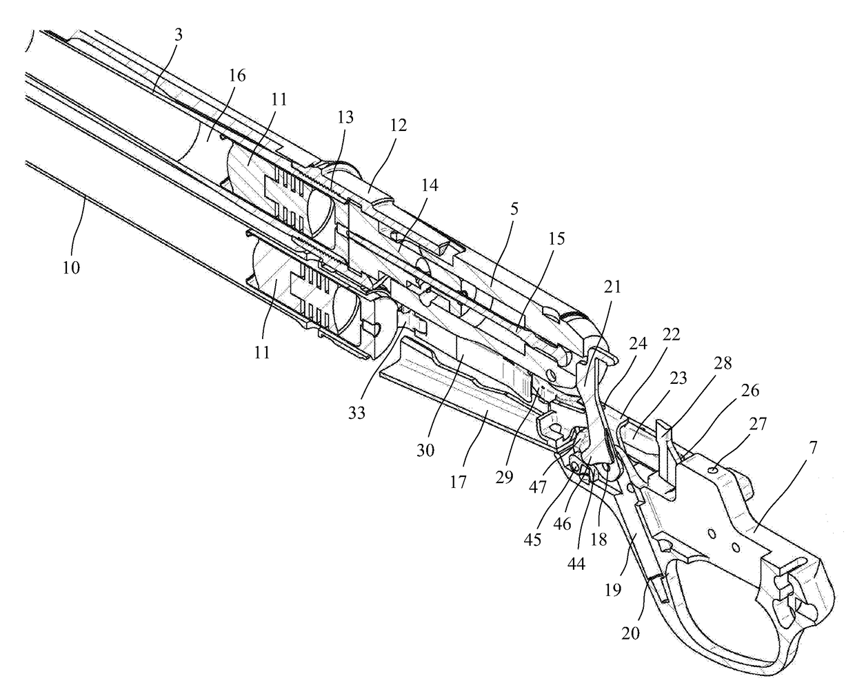
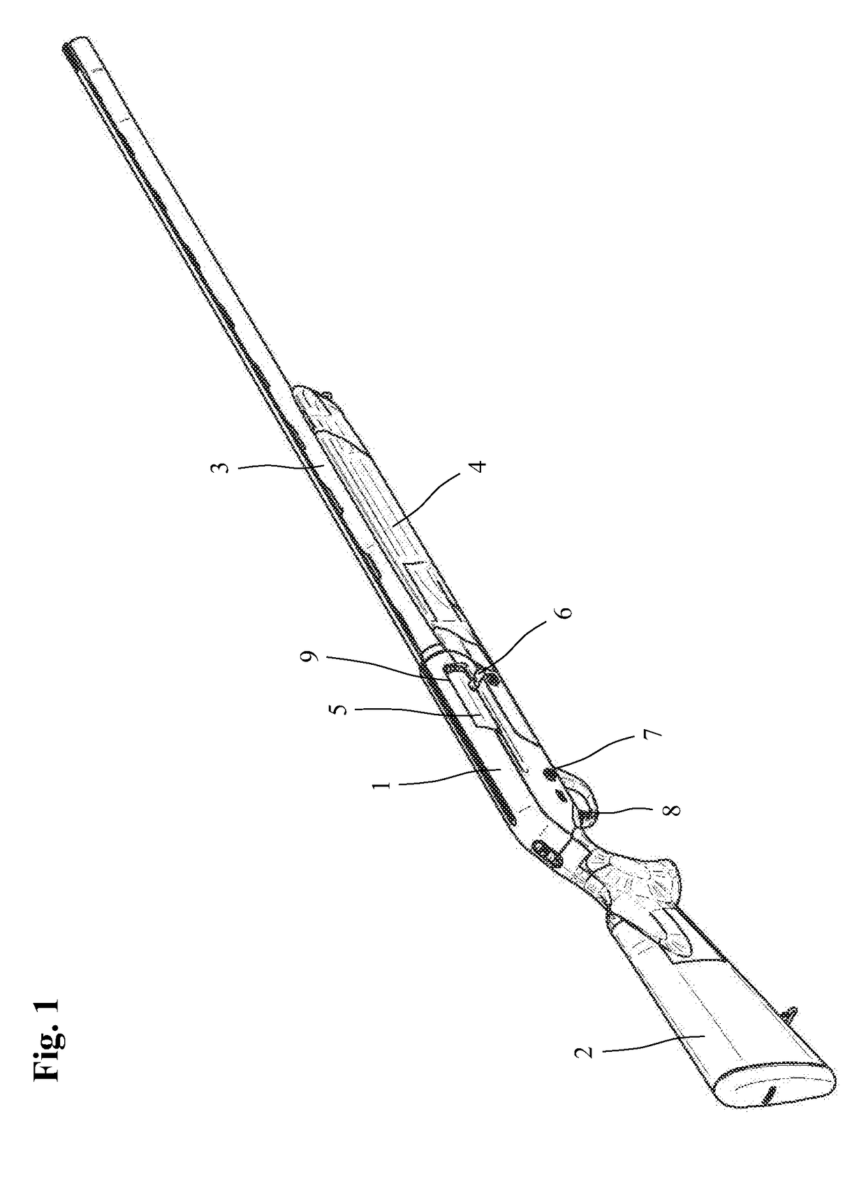
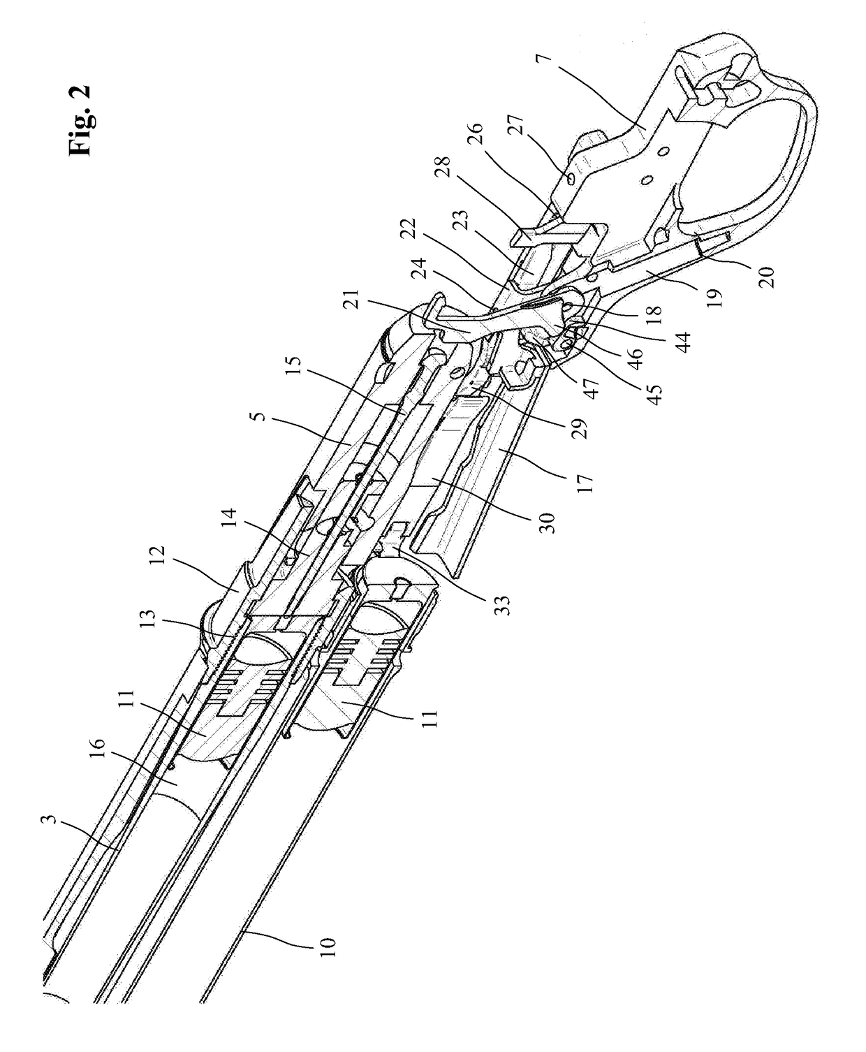
[0025]The self-loading firearm in the diagrammatic representation shown in FIG. 1 comprises a lock housing 1, also known as a system box, a stock 2 disposed on the rearward end of the lock housing 1, a barrel 3 projecting from the forward end of the lock housing 1, and a forearm 4 disposed below the barrel 3. In addition, the self-loading firearm, here configured in the form of a self-loading rifle, also comprises a locking system disposed inside the lock housing 1 with a lock carrier 5 that, in the longitudinal direction of the barrel 3, travels between an open position and a closed position and that, when a shot is fired, is pushed back by the recoil against a compression spring or can be manually actuated by means of a loading lever 6. The locking system further comprises a trigger carrier 7, also known as a locking plate, having a trigger guard, with a trigger 8 being disposed on the trigger carrier. The trigger carrier 7 is detachably affixed to the lower face of the lock housi...


PUM


Abstract

A self-loading shotgun includes a lock movable inside a lock housing between an open position and a closed position, a barrel, a magazine disposed below the barrel, a lock catch for holding the lock in the open position, and a feeder system for lifting a cartridge delivered from the magazine to the height of the barrel. The feeder system includes a feeder that swivels about a transverse axis and a magazine hatch that interacts with the lock catch. To allow the self-loading shotgun to be fully loaded even when the lock is open, the swivel movement of the feeder generated by the lock is controlled by a control element separate from the lock catch.

Description

FIELD OF THE DISCLOSURE[0001]The present disclosure relates to an auto-loading shotgun.BACKGROUND[0002]This type of auto-loading shotgun is known from US 2011 / 0308126 A1. It comprises a lock movable inside a lock housing between an open position and a closed position, a barrel, a magazine disposed below the barrel, and a feeder system for lifting a cartridge delivered from the magazine to the height of the barrel. The feeder system comprises a feeder consisting of two separate components, with a lower component that swivels about a transverse axis and the actual loading port that swivels independently of the lower component about the transverse axis. A lever interacting with the lock is hinged to the lower component of the feeder, which lever has a dual function. On the one hand, the lever hinged to the lower component of the feeder holds the lock in the open position and thereby functions as a lock catch when the lower component of the feeder is prevented from moving upwardly by a ...

Claims


Application Information

Patent Timeline
IPC IPC(8): F41A9/14F41A3/12F41A9/72F41C7/00
CPCF41A9/14F41C7/00F41A3/12F41A9/72F41A17/36F41A3/28F41A9/15F41A9/18
Inventor POPIKOV, SERGEJFESTER, EUGENWIEDEMANN, PETER
Owner L & O HUNTING GRP
Why Eureka
Try Eureka