Sealing device between an injection system and a fuel injection nozzle of an aircraft turbine engine

Active Publication Date: 2018-01-04
SN DETUDE & DE CONSTR DE MOTEURS DAVIATION S N E C M A
View PDF7 Cites 7 Cited by
  • Summary
  • Abstract
  • Description
  • Claims
  • Application Information

AI Technical Summary

Benefits of technology

[0013]Therefore the invention has the special feature that a sealing device is implanted between the injector nozzle and the guide, to avoid/limit risks of generation of an additional air flow towards the bottom of the combustion chamber. In general, the result is an increase in the performances and life of the combustion chamber.
[0014]This sealing device limits wear between the guide and the injector nozzle, and can judiciously be used as a wear i

Problems solved by technology

This wear is generated particularly by engine vibrations and is aggravated by misalignments of the injector relative to the injection system.
An undesirable clearance is then created between the guide and the injector nozzle during the life of the installation.
The main consequence of this clearance is the generation of an additional uncontrolled air flow towards the bottom of the combustion chamber.
In general, the result is a reduction in t

Method used


Image

  • Sealing device between an injection system and a fuel injection nozzle of an aircraft turbine engine
  • Sealing device between an injection system and a fuel injection nozzle of an aircraft turbine engine
  • Sealing device between an injection system and a fuel injection nozzle of an aircraft turbine engine

Examples


Embodiment Construction

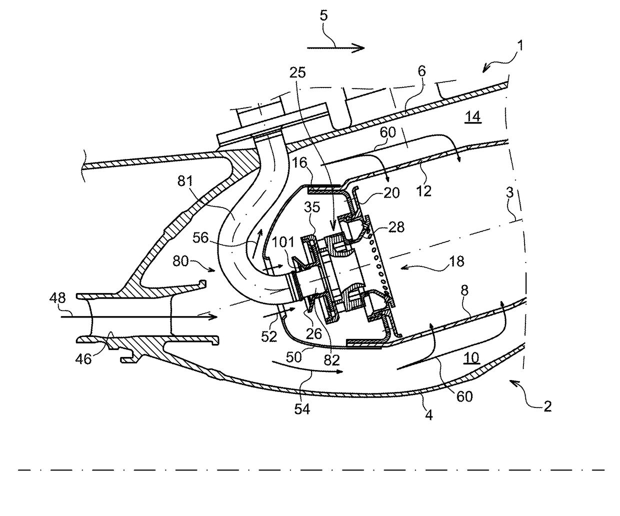
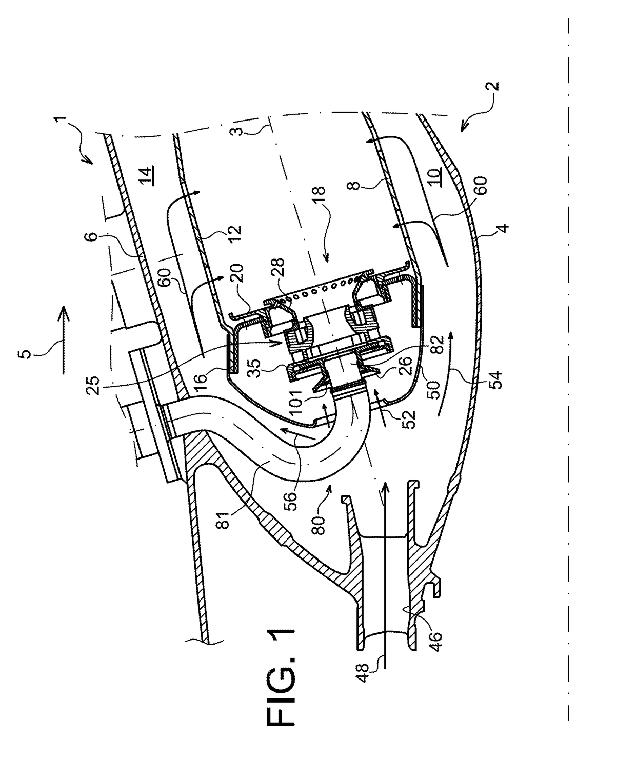
[0039]FIG. 1 diagrammatically represents a combustion chamber 2 of an aircraft turbine engine 1, that is annular in shape about an axis of the turbine engine. The combustion chamber 2 comprises a fixed inner casing wall 4 and an outer casing wall 6. The outer casing wall 6 and an outer chamber wall 12 delimit an air flow passage 14. The inner casing wall 4 and an inner chamber wall 8 delimit a second air flow passage 10. The inner chamber wall 8 and the outer chamber wall 12 are connected through the chamber bottom 16 of the combustion chamber 2.

[0040]Throughout this document, the “upstream” and “downstream” directions are defined with regard to the general direction of air and fuel flow in the combustion chamber 2, diagrammatically represented by the arrow 5. This direction also corresponds approximately to the flow direction of exhaust gases in the turbine engine 1.

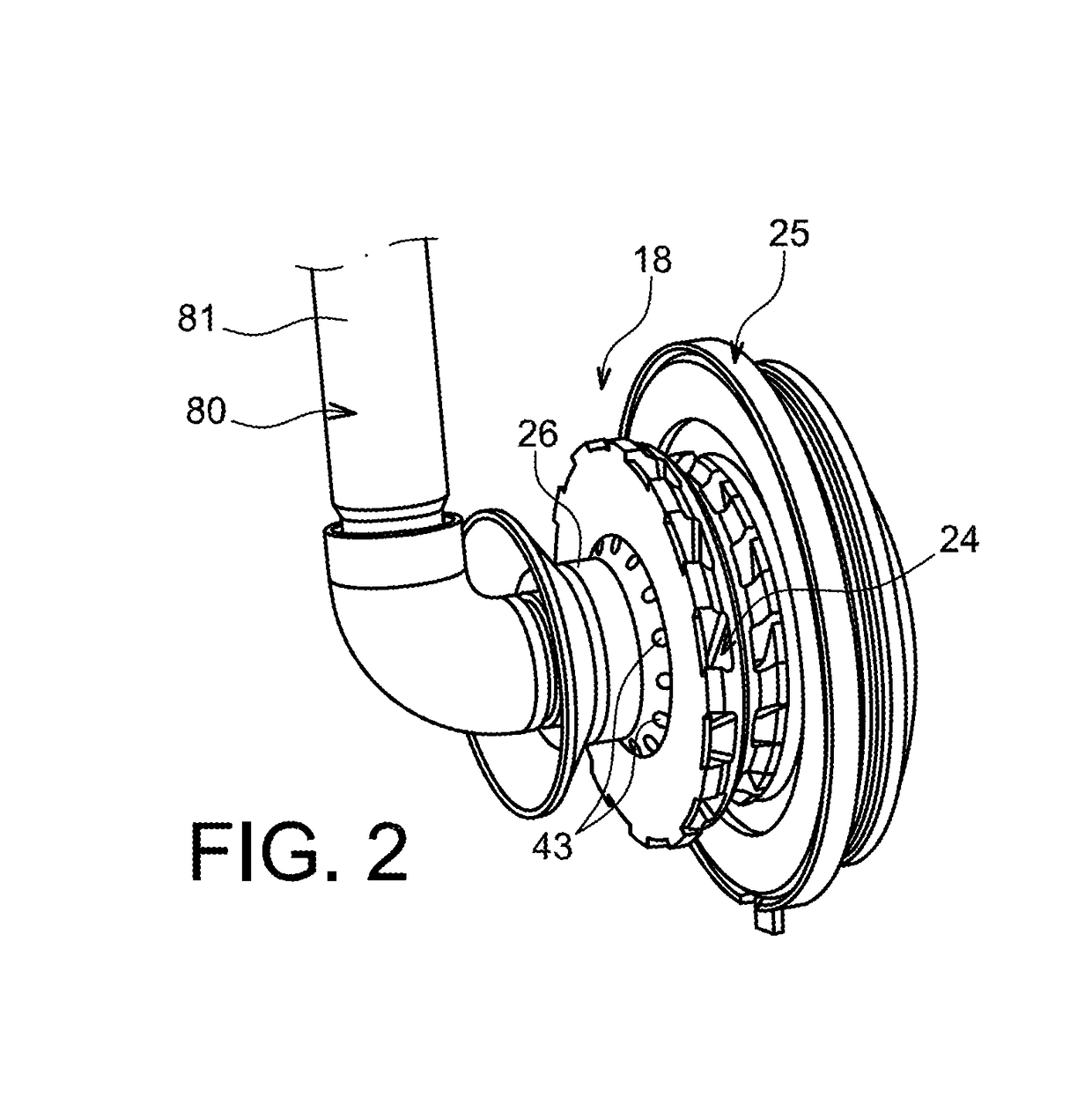
[0041]A plurality of injection systems 18 are fitted on the chamber bottom 16, only one of which is visible on FIG. 1...


PUM


Abstract

An arrangement for an aircraft turbine engine combustion chamber including an injection system and a fuel injector is provided. The injection system includes an injector nozzle guide, the inner surface of which delimits an opening for centering the nozzle, which includes an outer casing. The arrangement further includes a sealing device between the inner surface of the guide and the outer casing. The sealing device includes a first part accommodated in a groove of the outer casing, the groove being delimited, in part, by a downstream delimiting surface, the first part having a first sealing surface and bearing axially against the downstream delimiting surface; and a second part having a second sealing surface bearing radially against the inner surface of the guide.

Description

TECHNICAL DOMAIN[0001]The invention relates to the domain of combustion chambers for aircraft turbine engines. More specifically, the invention relates to fuel injectors and injection systems to inject an air-fuel mix for such turbine engine combustion chambers.STATE OF PRIOR ART[0002]A classical injection system of an air-fuel mix into an aircraft turbine engine combustion chamber is known for example through document EP 1 731 837 A2.[0003]The injection system comprises a part fixed relative to the combustion chamber. The fixed part comprises a mixer bowl fixed to a combustion chamber bottom, and a venturi and an air swirler. The venturi and the air swirler are located upstream from the mixer bowl.[0004]The injection system also comprises a sliding cross member free to move relative to the fixed part. The sliding cross-member, also called the “injection nozzle guide”, is configured to mechanically connect the fuel injector to the injection system. This guide is intended particularl...

Claims


Application Information

Patent Timeline
IPC IPC(8): F23R3/28F23D11/38F23R3/14F23R3/26
CPCF23R3/283F23R3/14F23R3/286F23R3/26F23D11/383F05D2240/55F23R2900/00012F23R3/28
Inventor RODRIGUES, JOSE ROLANDCHABAILLE, CHRISTOPHE
Owner SN DETUDE & DE CONSTR DE MOTEURS DAVIATION S N E C M A
Why Eureka
Try Eureka