Self-sensing touch panel

a touch panel and self-sensing technology, applied in the direction of instruments, electric digital data processing, input/output process of data processing, etc., can solve the problems of not being able to sense multiple touch events at the same time, touch events may be missed, non-events may be misinterpreted, etc., to improve the sensitivity to noise fluctuations, increase the signal-to-noise ratio of sense lines, and increase the effect of touch sensor accuracy

Active Publication Date: 2018-01-04
STMICROELECTRONICS ASIA PACIFIC PTE
View PDF3 Cites 14 Cited by
  • Summary
  • Abstract
  • Description
  • Claims
  • Application Information

AI Technical Summary

Benefits of technology

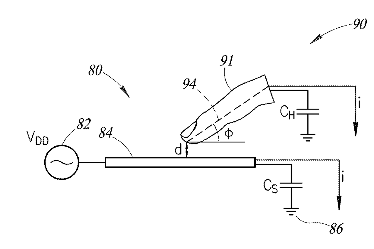
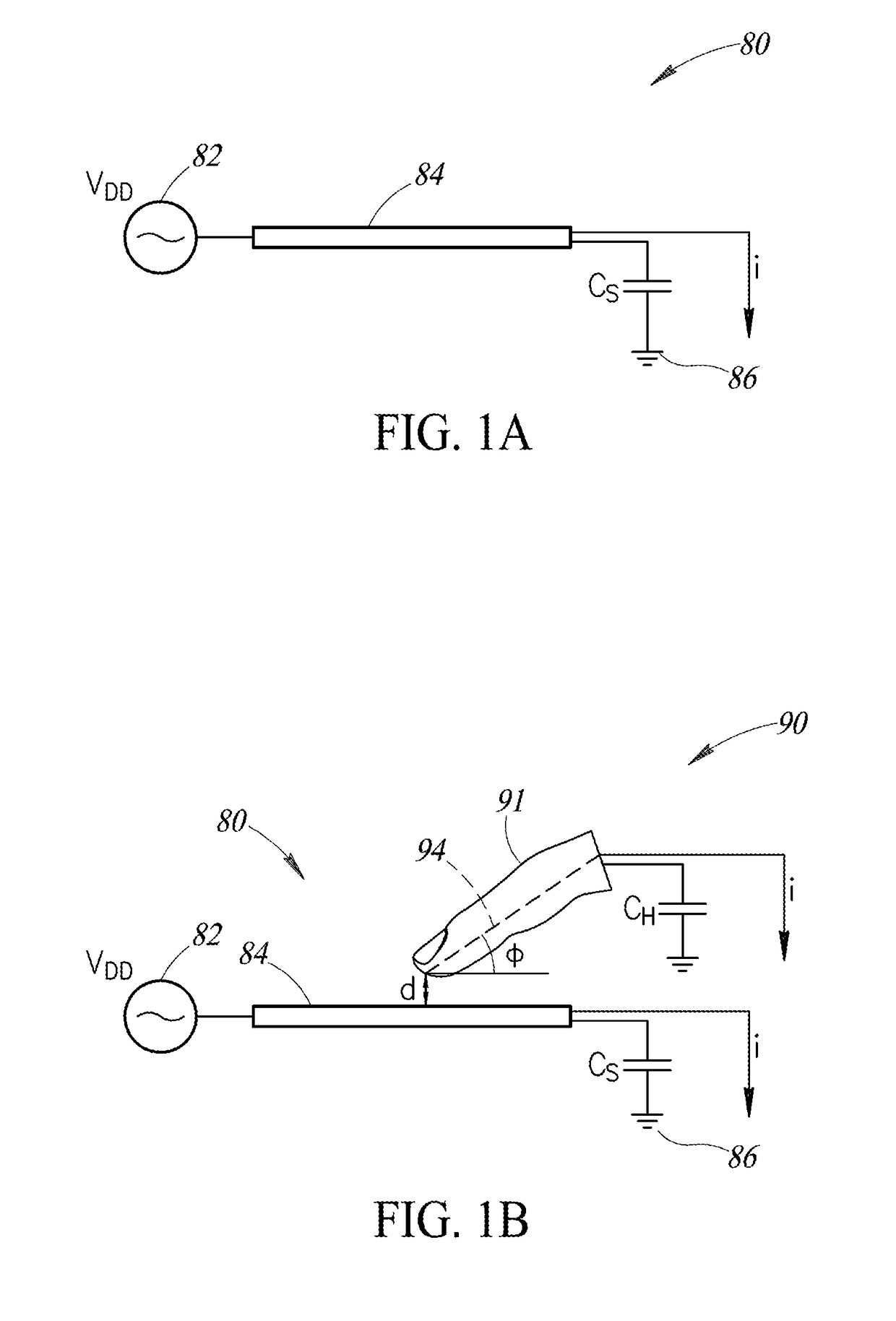
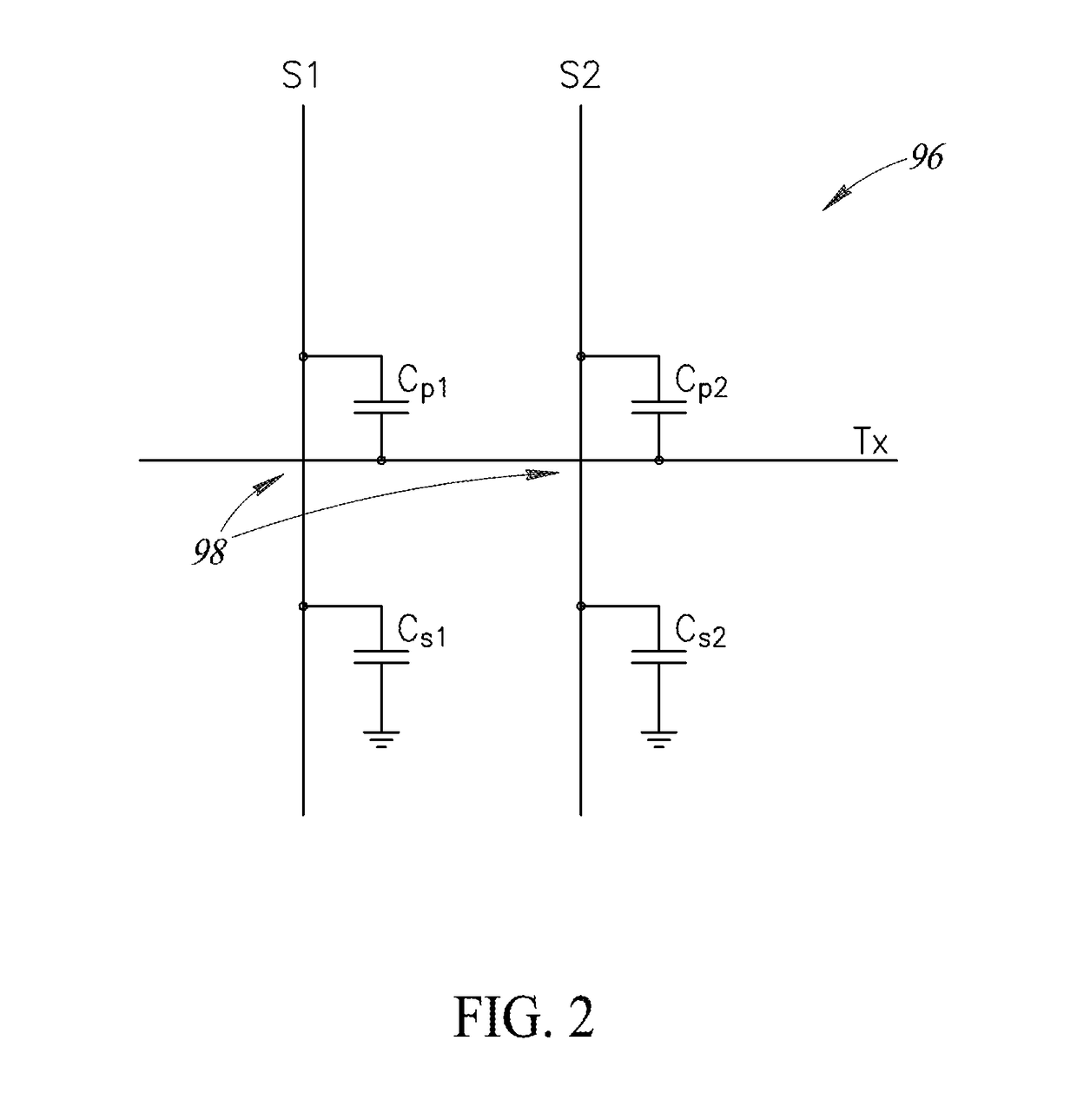
[0004]A method of differential capacitance measurement is used to enhance a signal-to-noise ratio of sense lines in a touch panel, thereby increasing touch sensor accuracy over methods that use absolute capacitance measurements. The differential capacitance measurement is a normalized electrical signal value that provides greater sensitivity to noise fluctuations. An increase in sensitivity occurs because differential measurement values are much smaller than absolute measurement values.

Problems solved by technology

However, in some instances, touch events may be missed, or non-events may be misinterpreted as touch events.
For example, certain touch panels may not be able to sense multiple touch events at the same time.
Furthermore, a self-capacitance detection method may fail to sense a finger hovering above the touch panel.
Water droplets falling on the touch panel may be erroneously interpreted as touch events.

Method used


Image

  • Self-sensing touch panel
  • Self-sensing touch panel
  • Self-sensing touch panel

Examples


Embodiment Construction

[0017]In the following description, certain specific details are set forth in order to provide a thorough understanding of various aspects of the disclosed subject matter. However, the disclosed subject matter may be practiced without these specific details. In some instances, well-known structures and methods comprising embodiments of the subject matter disclosed herein have not been described in detail to avoid obscuring the descriptions of other aspects of the present disclosure.

[0018]Unless the context requires otherwise, throughout the specification and claims that follow, the word “comprise” and variations thereof, such as “comprises” and “comprising,” are to be construed in an open, inclusive sense, that is, as “including, but not limited to.”

[0019]Reference throughout the specification to “one embodiment” or “an embodiment” means that a particular feature, structure, or characteristic described in connection with the embodiment is included in at least one embodiment. Thus, t...


PUM


Abstract

A method of differential self-capacitance measurement is used to enhance a signal-to-noise ratio of sense lines in a touch panel display, thereby improving touch sensor accuracy. The differential self-capacitance measurement is implemented for a touch panel using charge sharing between adjacent sense lines of the touch panel matrix. Sequential differential self-capacitance measurements can be compared with one another by computing the difference |CS1−CS2|−|CS2−CS1| to sense a change caused by an intervening event. By scanning the entire touch panel matrix, events can be tracked across the touch panel.

Description

BACKGROUNDTechnical Field[0001]The present disclosure relates to touch screen technology and, in particular, to improving the sensitivity of touch screens.Description of the Related Art[0002]Touch screens serve as user interfaces for many types of electronic devices in use today including, for example, smart phones, tablet computers, kiosks, vehicle control panels, and the like. A touch screen includes a touch-sensitive panel overlaid on a display. The display provides visual output to users of the electronic device. The display also presents text and graphics indicating selections, e.g., web links, play buttons, and the like, that can be activated by contact with the overlying touch-sensitive panel. Displays utilize various display technologies such as, for example, liquid crystals (LCD), plasma, organic light emitting diodes (OLED), and the like.[0003]A touch-sensitive panel, or “touch panel,” typically includes a matrix of drive lines and sense lines arranged transverse to one an...

Claims


Application Information

Patent Timeline
Patent Type & Authority Applications(United States)
IPC IPC(8): G06F3/041G06F3/044
CPCG06F3/0418G06F2203/04101G06F2203/04104G06F3/044G06F3/0412G06F3/04182
Inventor GICQUEL, HUGONG, ENGJYE
Owner STMICROELECTRONICS ASIA PACIFIC PTE
Why Eureka
Try Eureka