Pufs from sensors and their calibration

a technology of sensors and sensors, applied in the field of cybersecurity, can solve problems such as the vulnerability of sensor based systems that are connected to the web

Active Publication Date: 2018-01-04
ARIZONA BOARD OF REGENTS ACTING FOR & ON BEHALF OF NORTHERN ARIZONA UNIV
View PDF5 Cites 19 Cited by
  • Summary
  • Abstract
  • Description
  • Claims
  • Application Information

AI Technical Summary

Benefits of technology

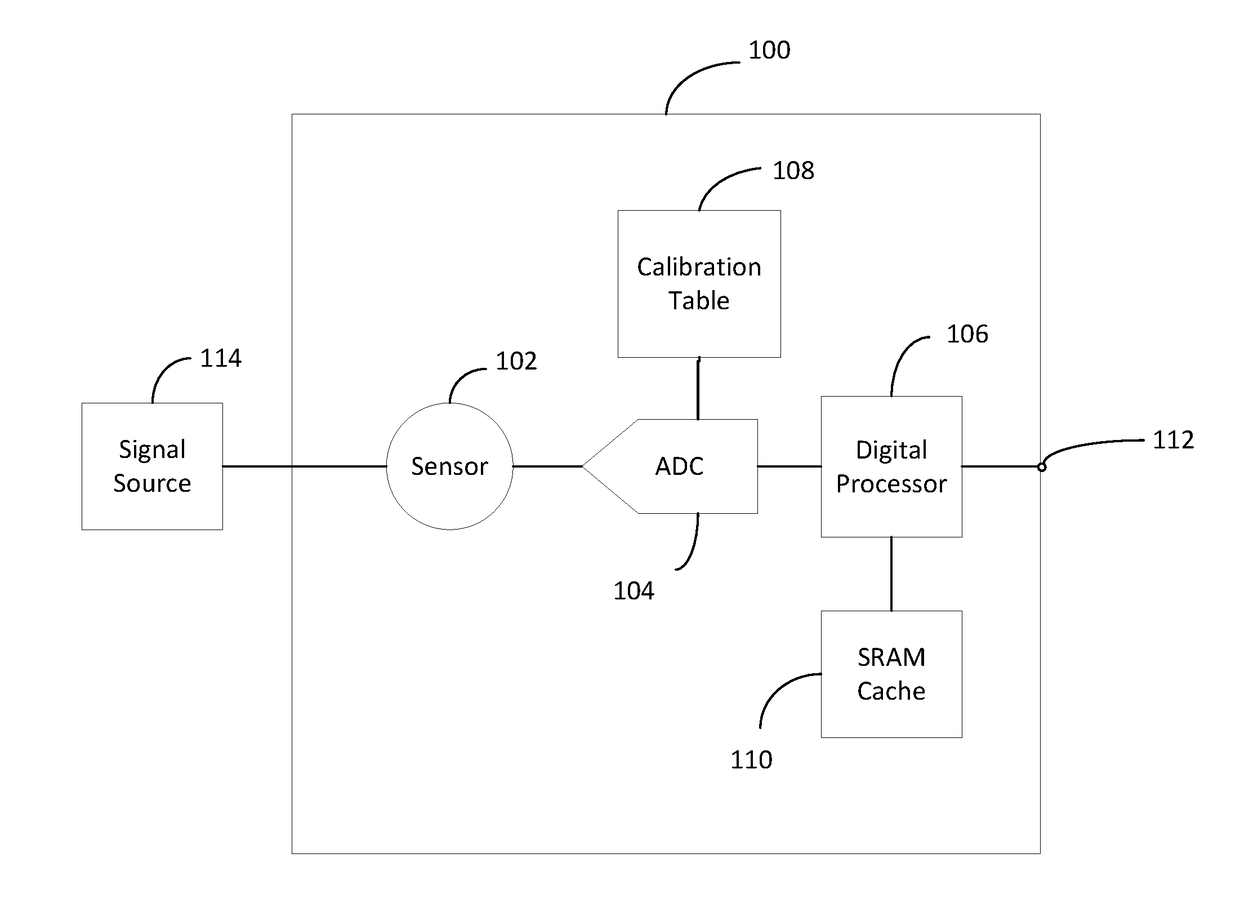
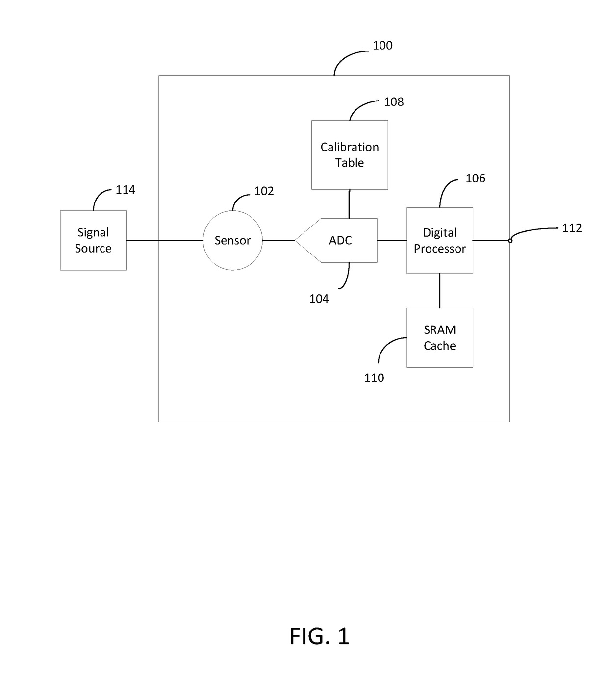
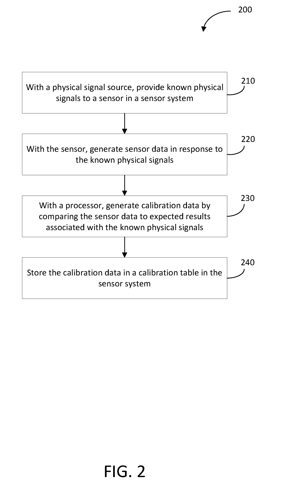
[0007]The first architecture disclosed herein is based on the extraction of a stream of bits from the calibration table of each sensor to generate reference patterns, called PUF challenges, which can be stored in secure servers. The authentication of the sensor is positive when the data streams that are generated on demand, called PUF responses, match the challenges. To prevent a malicious party from generating responses, instructions can be added as part of the PUF challenges to define which parts of the calibration tables are to be used for response generation, and what additional responses can be generated by the embedded RAMs.

Problems solved by technology

Sensor based systems that are connected to the web are often vulnerable to cyber-attacks which could trigger life threatening conditions.

Method used


Image

  • Pufs from sensors and their calibration
  • Pufs from sensors and their calibration
  • Pufs from sensors and their calibration

Examples


example # 1

Example #1: Securing the Smart Grid

[0083]Uncalibrated current sensors (magnetometers) paired with calibrated sensors can be installed at every node of a grid. The hamming distance between the two output signals responding to a reference current Iref are the challenges and may be stored in the secure server managing the network. To authenticate a particular node, the reference current Iref is sent again to the node and the response to the current sensors is analyzed for CRP matching. This method can authenticate each sensor and conversely can be used at the node level to authenticate the network; in this last case the authentication is done by a secure processor that is part of the node.

example # 2

Example #2: User Authentication

[0084]Each user is given a token that includes a pair of 3D magnetic sensors, and a small wireless communication apparatus. For authentication the user may place the token on a transmitter of a magnetic field of known amplitude that is located at the point of entry of a secure facility. The sensor placed in the token will read the magnetic field and transmit back the response to the transmitter for the CRP analysis which is done by the server of the secure facility. The identification of the user is preferably done with a different method that is synergistic with this authentication.

example # 3

Example #3: Authentication of Smart Phones

[0085]Commercial smart phones incorporate multiple sensors such as accelerometers, gyroscopes, and magnetometers. The insertion of uncalibrated sensors as part of these embedded sensors can continuously generate responses for authentication that are tracking the signal produced by the calibrated sensors. It becomes then possible to authenticate each smart phone by their PUF sensor for the purpose of digital rights management, anti-theft, and software protection.


PUM


Abstract

Several methods may be used to exploit the natural physical variations of sensors, to generate cryptographic physically unclonable functions (PUF) that may strengthen the cybersecurity of microelectronic systems. One method comprises extracting a stream of bits from the calibration table of each sensor to generate reference patterns, called PUF challenges, which can be stored in secure servers. The authentication of the sensor is positive when the data streams that are generated on demand, called PUF responses, match the challenges. To prevent a malicious party from generating responses, instructions may be added as part of the PUF challenges to define which parts of the calibration tables are to be used for response generation. Another method is based on differential sensors, one of them having the calibration module disconnected. The response to a physical or chemical signal of such a sensor may then be used to authenticate a specific pair of sensors.

Description

CROSS-REFERENCES TO RELATED APPLICATIONS[0001]The present application claims priority from and benefit of U.S. Provisional Patent Application No. 62 / 356,468 filed on Jun. 29, 2016. The disclosure of the above-identified patent application is incorporated by reference herein in its entirety.FIELD OF THE INVENTION[0002]The present invention generally relates to cybersecurity and more specifically to creating and authenticating physically unclonable functions (PUFs) which may be a calibrated sensor or a pair of sensors.BACKGROUND[0003]Sensors convert physical and / or chemical signals into electric signals driving microelectronic systems. In order to generate electric signals that accurately represent the physical or chemical signals, calibration techniques have to compensate for the natural variations which are created during the manufacturing of the sensors.[0004]Sensor based systems that are connected to the web are often vulnerable to cyber-attacks which could trigger life threatenin...

Claims


Application Information

Patent Timeline
Patent Type & Authority Applications(United States)
IPC IPC(8): H04L9/32G06F11/22G06F12/14H04L29/06
CPCH04L9/3278G06F11/2268G06F2212/1052H04L63/1425G06F12/1408G06F21/44G06F21/73G06F2221/2129H04W84/18H04W12/06G06F21/00
Inventor CAMBOU, BERTRAND FRANCIS
Owner ARIZONA BOARD OF REGENTS ACTING FOR & ON BEHALF OF NORTHERN ARIZONA UNIV
Why Eureka
Try Eureka