
Flameless thermal oxidizer and related method of shaping reaction zone

a technology of reaction zone and flameless thermal oxidizer, which is applied in the direction of exothermal chemical reaction heat production, combustion types, lighting and heating apparatus, etc., can solve the problems of limited flow capacity and limited reaction stability within the fto

Inactive Publication Date: 2018-01-11
LINDE ENG NORTH AMERICA
View PDF0 Cites 1 Cited by
  • Summary
  • Abstract
  • Description
  • Claims
  • Application Information

AI Technical Summary

Benefits of technology

The patent describes a flameless thermal oxidizer (FTO) with a baffle that is placed in the reactive chamber of the FTO. This baffle works with a diptube to expand the reaction bubble or envelope outward into a porous matrix. This helps to control the reaction and improve yields. The technical effect of this is better control over the reaction process in the FTO, resulting in higher yields of desired products.

Problems solved by technology

However, such arrangements result in a limited flow capacity and limited reaction stability within the FTO.

Method used


Image

  • Flameless thermal oxidizer and related method of shaping reaction zone
  • Flameless thermal oxidizer and related method of shaping reaction zone
  • Flameless thermal oxidizer and related method of shaping reaction zone

Examples


Embodiment Construction

[0015]Before explaining the inventive embodiments in detail, it is to be understood that the invention is not limited in its application to the details of construction and arrangement of parts illustrated in the accompanying drawings, if any, since the invention is capable of other embodiments and being practiced or carried out in various ways. Also, it is to be understood that the phraseology or terminology employed herein is for the purpose of description and not of limitation.

[0016]In the following description, terms such as a horizontal, upright, vertical, above, below, beneath and the like, are to be used solely for the purpose of clarity, illustrating the invention and should not be taken as words of limitation. The drawings are for the purpose of illustrating the invention and are not intended to be to scale.

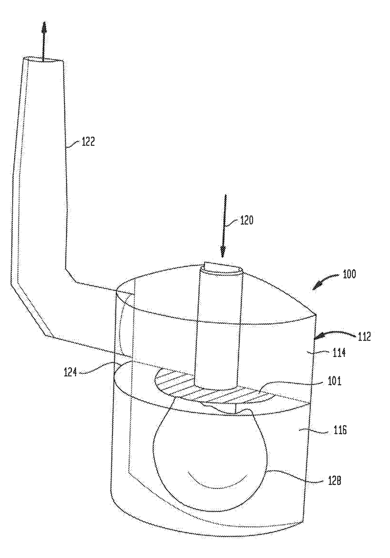
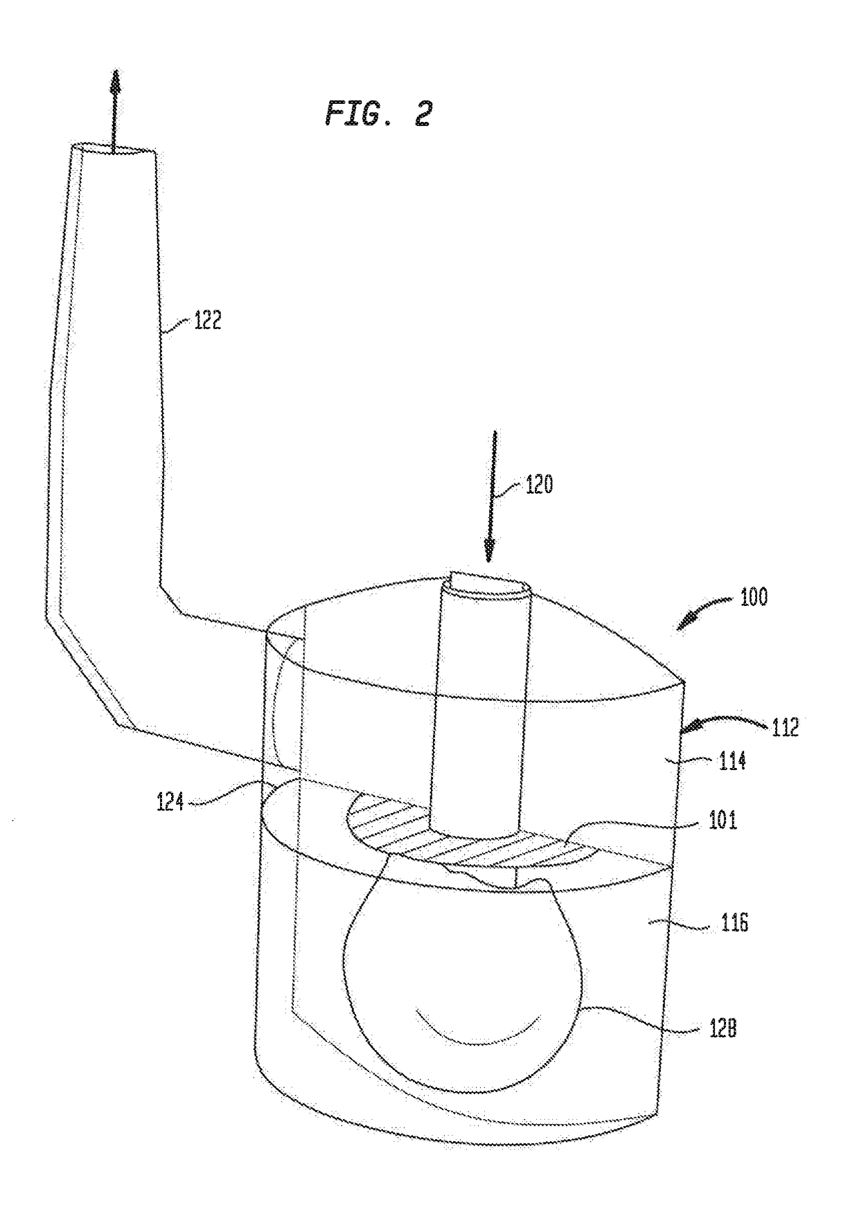
[0017]In general, and in an FTO of the present embodiments beginning at FIG. 2, the introduction of impermeable or semi-permeable baffles surrounding the diptube of the F...


PUM


Abstract

A flameless thermal oxidizer (FTO) includes at least one baffle constructed and arranged in a reaction chamber of the FTO to coact with a diptube of the FTO to radially expand a resulting “bubble” or reaction envelope from the diptube outward into a porous matrix of the FTO. A related method is also provided.

Description

BACKGROUND OF THE INVENTION[0001]The present embodiments relate to baffles for a flameless thermal oxidizer (FTO), and a method of increasing capacity with the FTO.[0002]Known FTOs have been used to maintain an oxidation reaction of gaseous waste stream(s) within a matrix of the FTO. However, such arrangements result in a limited flow capacity and limited reaction stability within the FTO. This is because the overcapacity reaction envelope or “reaction bubble” produced from the FTO diptube permits the incomplete oxidation reaction products to flow rapidly upward to and break or pierce through the top surface of the FTO matrix.[0003]An example of a known FTO is shown in FIG. 1 and referenced generally as 10. The known FTO is a flameless matrix bed reactor which includes a vessel 12 or container in which a reaction chamber 14 is disposed. A porous matrix 16 is arranged in the reaction chamber 14, but does not completely fill the chamber. A diptube 18 extends into the reaction chamber ...

Claims


Application Information

Patent Timeline
IPC IPC(8): F23C99/00F24J1/00B01J8/00B01J8/02
CPCF23C99/006F24J1/00B01J8/008B01J2208/00796B01L2200/06B01L2200/028B01J8/02F23D14/70F23D14/84F23C2900/99001F23G2209/14F24V30/00Y02E20/34
Inventor IRRGANG, GENE H.PREDATSCH, ERICRICHARDSON, ANDREWKORN, STEVE
Owner LINDE ENG NORTH AMERICA
Learn More