
Wireless positioning pen with pressure-sensitive tip

a wireless positioning pen and tip technology, applied in the direction of instruments, electric digital data processing, data processing input/output processes, etc., can solve problems such as art disadvantages, and achieve the effect of convenient replacemen

Active Publication Date: 2018-01-11
O PEN
View PDF0 Cites 13 Cited by
  • Summary
  • Abstract
  • Description
  • Claims
  • Application Information

AI Technical Summary

Benefits of technology

The wireless positioning pen with the pressure-sensitive tip allows users to accurately position devices with a compact design that doesn't require additional sensing units or cameras. Users can opt for a 3D motion positioning function or a single press / double press button function depending on the intensity of the force applied to the tip button. The pen also has a writing mode for comfortable text writing. The device is powered by a single battery that is easily replaceable. Overall, the wireless positioning pen provides users with a convenient and efficient tool for positioning and controlling various devices.

Problems solved by technology

The disadvantages of the art are, to a substantial extent, removed by the wireless positioning pen with a pressure-sensitive tip, wherein the second cover is provided on the rear side of the casing, and the top part is provided with holes with fingerboards for buttons.

Method used


Image

  • Wireless positioning pen with pressure-sensitive tip
  • Wireless positioning pen with pressure-sensitive tip
  • Wireless positioning pen with pressure-sensitive tip

Examples


Embodiment Construction

OF EMBODIMENTS

[0058]The invention will now be described in detail regarding the embodiments of the wireless positioning pen with the pressure-sensitive tip with reference to relevant drawings. The examples illustrate the unlimited embodiment variations of the positioning pen according to the invention.

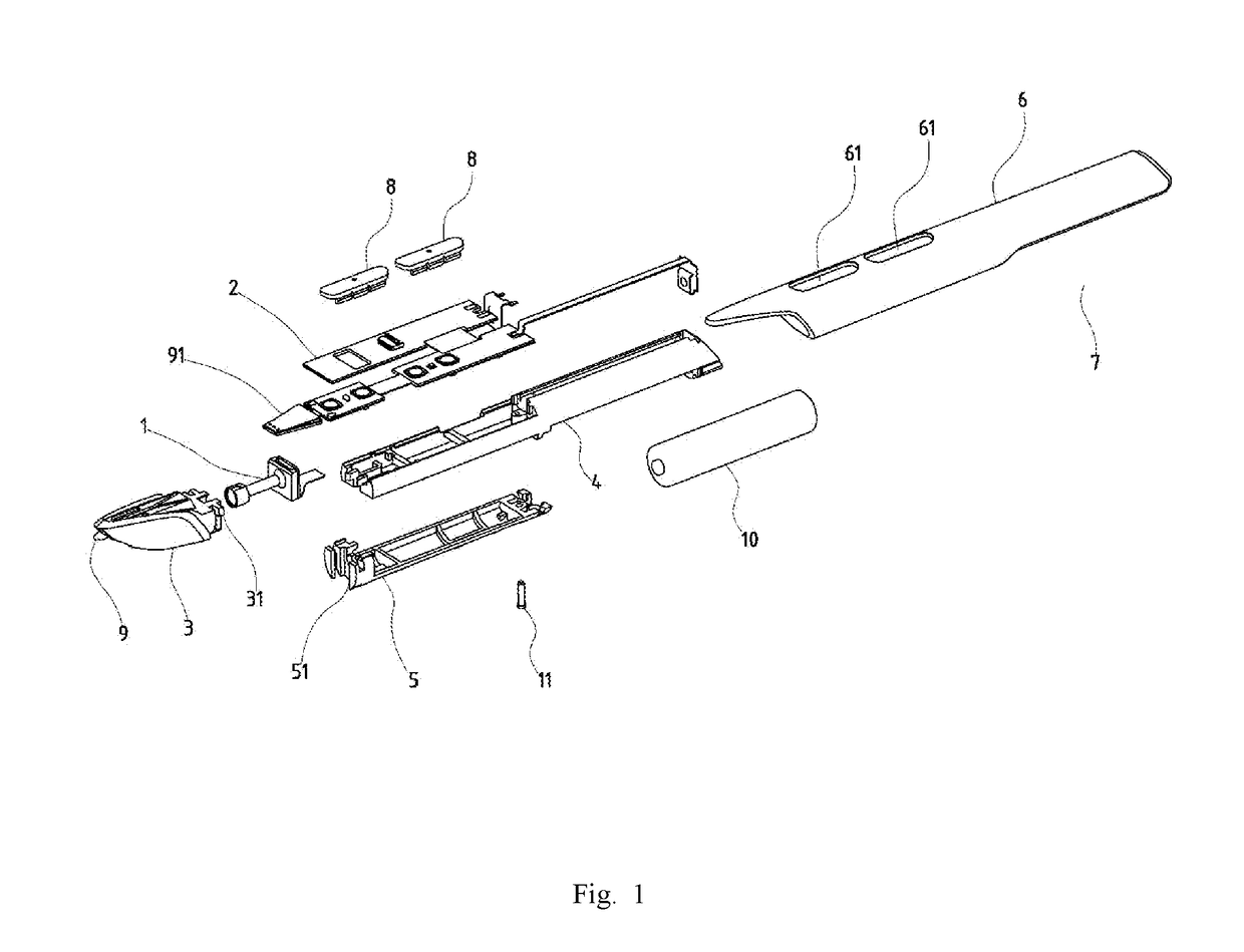
[0059]The example embodiment of the multi-functional pen controller with the pressure-sensitive tip is illustrated in the attached drawings. According to FIG. 1, the wireless positioning pen with the pressure-sensitive tip comprises the casing 6 with the second cover 7 for the battery 10 in the rear part. The casing 6 has either a circular or round shape being universal for comfortable handling by left-handers and right-handers. Furthermore, the casing 6 is provided on the upper part with holes 61 for placing fingerboards 8 on the buttons. The fingerboards 8 on the buttons are designed as two-way with a position that is comfortable for both left-handers and right-handers. The structure...


PUM


Abstract

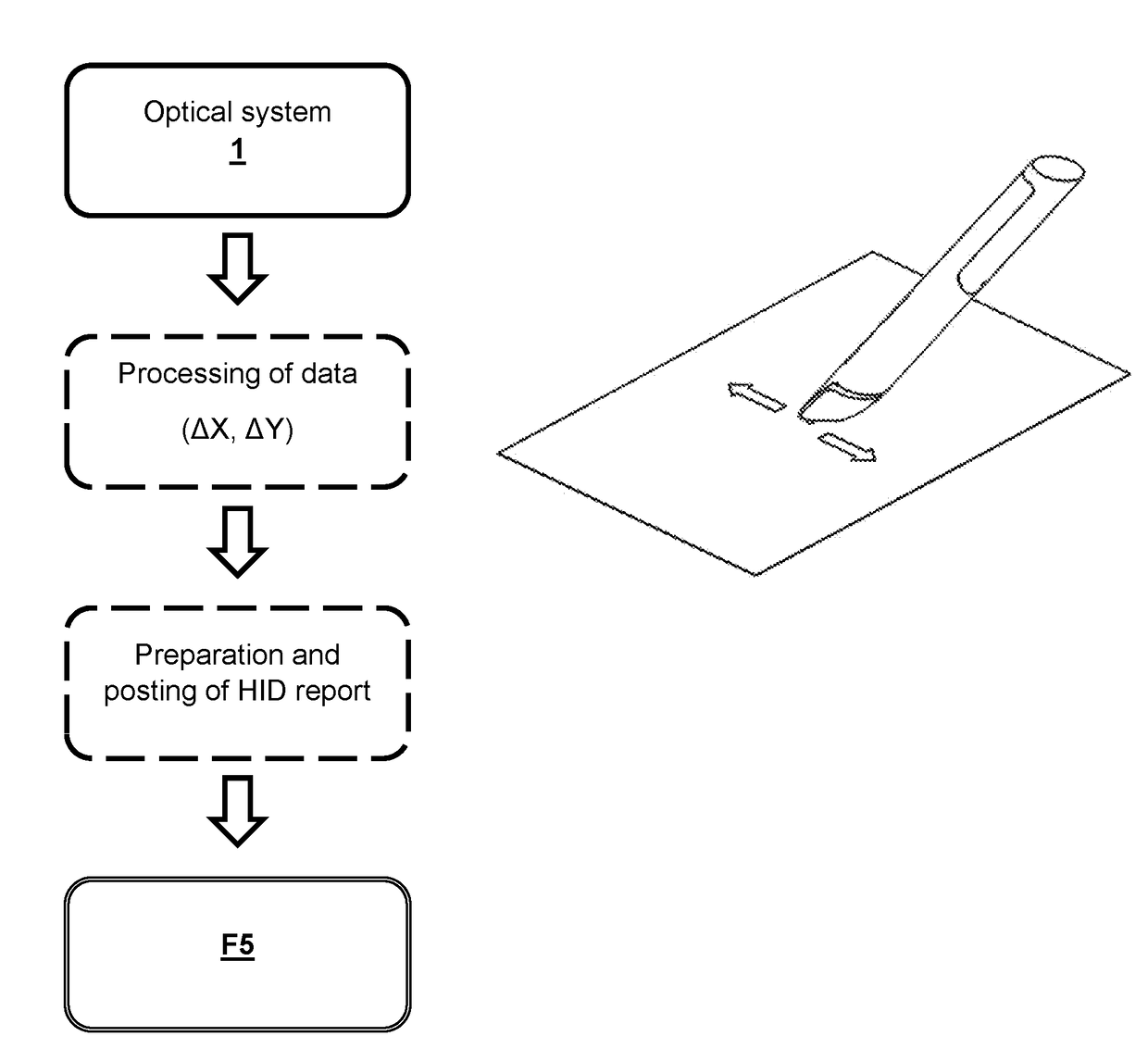
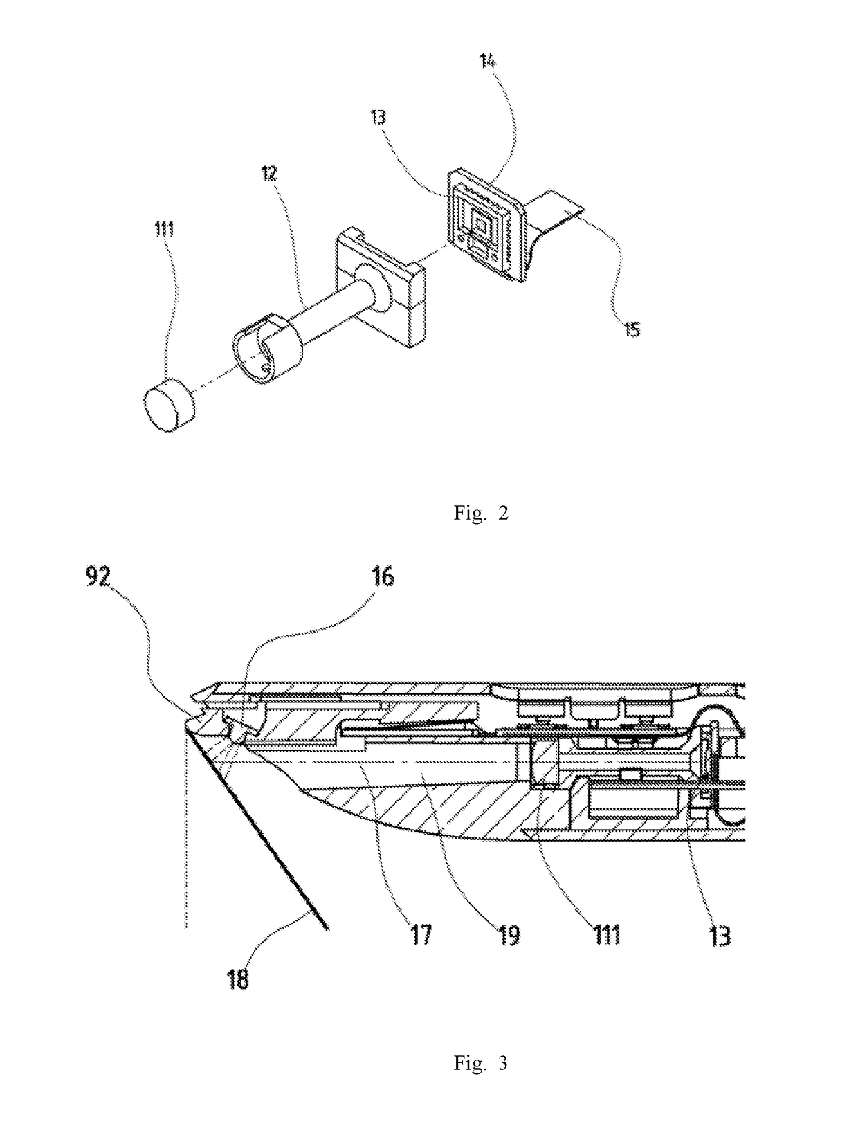
The present invention relates to a wireless positioning pen with a pressure-sensitive tip comprising an electric power source, optical system (1), inertial sensors and Bluetooth wireless technology, in which a casing (6) is provided with the second casing (7) in the rear, and the top part is provided with holes (61) with fingerboards (8) with buttons; said casing (6) provides a sliding housed body (4) with a battery (10) therein, a head (3) is attached to the front part thereof, and the first cover is (5) provided with a fastening mechanism (51) attached to lower part of the body (4), wherein the said body (4) houses a printed circuit board (2) consisting of the first fixed part (21), the second fixed part (22), the third fixed part (23), and the fourth fixed part (24) mutually interconnected with flexible parts (20), wherein the front body (4) part is provided with the optical system (1) configured for sliding thereof on the PCB fixed part (14) bearing the optical sensor (13) connected through the PCB flexible part (15) to the fourth fixed part (24), wherein the head (3) is provided with a tip button (92) with a light source (16), and in addition, a capacitive sensor (91).

Description

FIELD OF THE INVENTION[0001]The present invention relates to the arrangement of a wireless positioning pen with a pressure-sensitive tip for wireless control of computers, computing devices, multimedia devices, mobile phones, tablets, and other smart devices provided with Bluetooth wireless technology or USB.BACKGROUND OF THE INVENTION[0002]At present, a peripheral device, the so-called “X-Y” position indicator, generally known as a “mouse”, is most often used for simple and quick control of computers. Special sensors are used to transfer the motion of the position indicator onto the cursor movement on the computer monitor. A traditional mechanical-optical mouse is known, which enables to enter 2D information with the position sensor in the form of a revolving ball arranged on the bottom part of the mouse. Furthermore, the peripherals combined with a graphic display known as an “optical pen” are known. This device enables creative intervention into an image in the computer.[0003]SK ...

Claims


Application Information

Patent Timeline
IPC IPC(8): G06F3/0346G06F3/0354G06F3/044
CPCG06F3/0346G06F3/03545G06F2203/0384G06F3/038
Inventor MIHAL, MAREKMIHAL, ALEXANDR
Owner O PEN
Learn More