Deceleration hysterisis measuring apparatus for soft recovery system

Active Publication Date: 2018-01-18
AGENCY FOR DEFENSE DEV
View PDF9 Cites 0 Cited by
  • Summary
  • Abstract
  • Description
  • Claims
  • Application Information

AI Technical Summary

Benefits of technology

[0025]Further, even in a case where a projectile is jammed and stopped in the pressure tube of the soft recovery system, the position of

Problems solved by technology

Major components employed to a fuze sensor for mounting to a shell have to be made smaller due to a restricted design of the shell, and require a normal operation even in high shock environments such as a shell-firing environment.
However, since a system or components thereof for checking shock resistance and a conventional deceleration hysteresis measuring apparatus cannot be mounted on the same position in the test specimen projectile, there is a limit to measure in real-time deceleration hyster

Method used


Image

  • Deceleration hysterisis measuring apparatus for soft recovery system
  • Deceleration hysterisis measuring apparatus for soft recovery system
  • Deceleration hysterisis measuring apparatus for soft recovery system

Examples


Example

[0030]Reference should be made to the accompanying drawings and relevant description thereof for illustrating embodiments of the present disclosure in order to fully understand the present disclosure and operative advantages and objectives thereof

[0031]Repeated descriptions and descriptions of known functions and configurations that have been deemed to make the gist of the present disclosure unnecessarily obscure will be omitted below. The embodiments of the present disclosure are intended to fully describe the present disclosure to a person having ordinary knowledge in the art to which the present disclosure pertains. Accordingly, the shapes, sizes, etc. of components in the drawings may be exaggerated to make the description clearer.

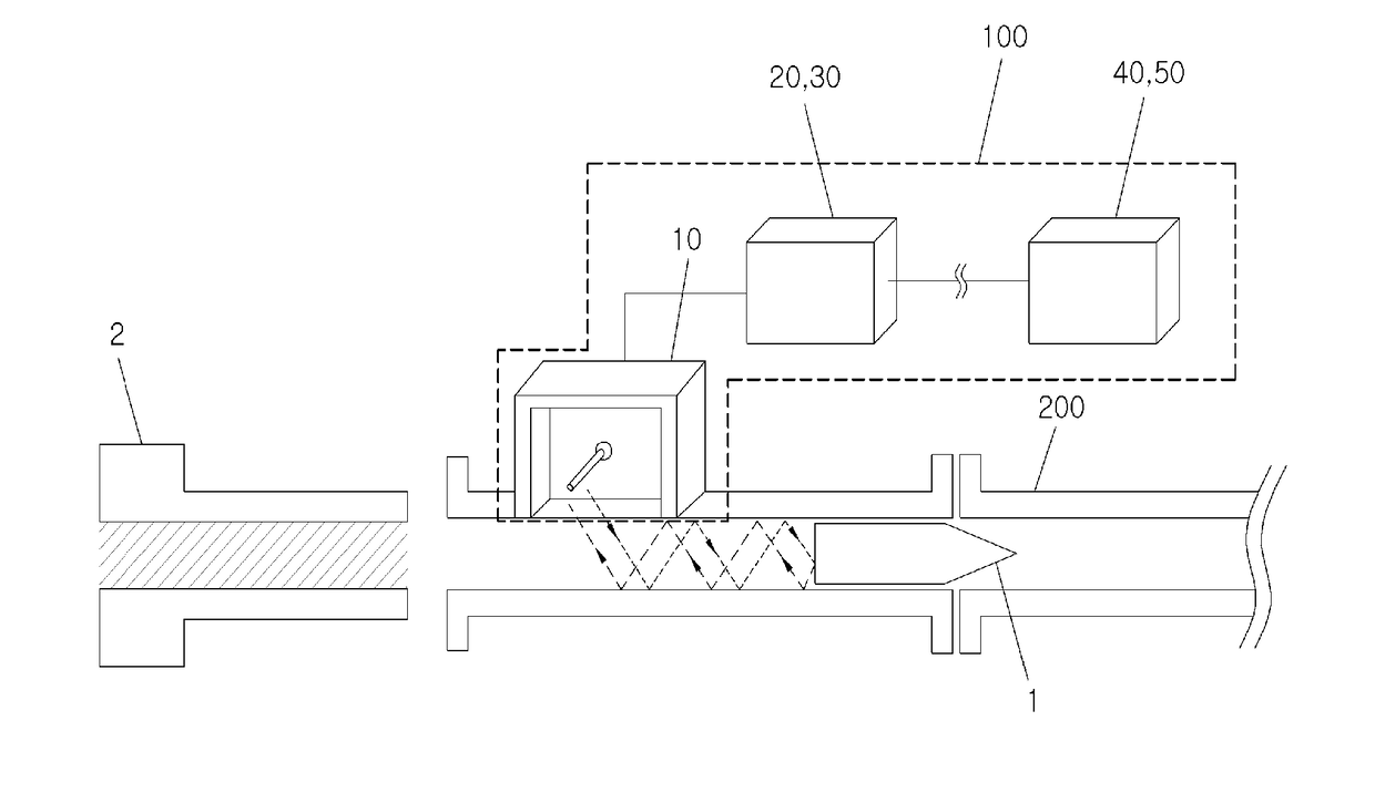
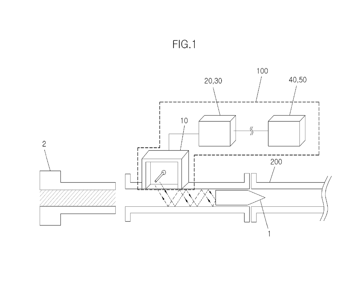
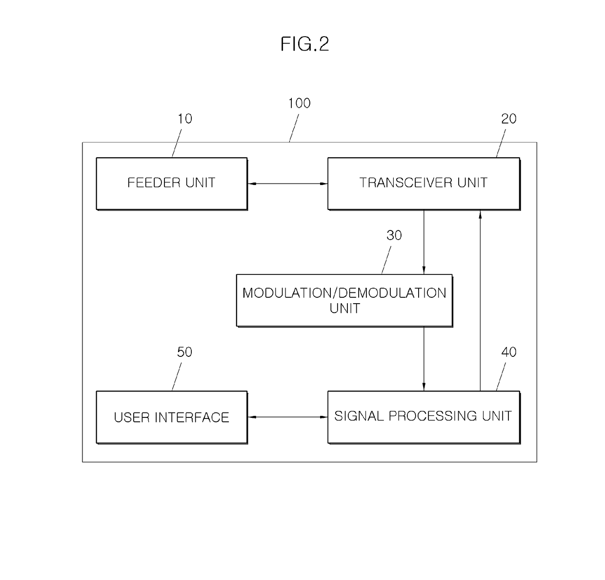
[0032]FIG. 1 is a conceptual view of a deceleration hysteresis measuring apparatus for a soft recovery system according to an embodiment of the present disclosure, FIG. 2 is a block diagram of the deceleration hysteresis measuring apparatus, and FIG. 3...


PUM


Abstract

A deceleration hysteresis measuring apparatus for a soft recovery system is configured to transmit an electromagnetic wave to a pressure tube of the soft recovery system and receive the electromagnetic wave reflected from a projectile moving in the pressure tube so as to measure a distance of the projectile based on signals of the transmitted and received waves.

Description

CROSS REFERENCE TO RELATED APPLICATION(S)[0001]This application claims the benefit of Korean Patent Application No.10-2016-0089226, filed Jul. 14, 2016, which is hereby incorporated by reference in its entirety into this application.BACKGROUND OF THE INVENTION1. Technical Field[0002]The present disclosure relates generally to a deceleration hysteresis measuring apparatus for a soft recovery system and, more particularly, to a deceleration hysteresis measuring apparatus that is installed in a soft recovery system to measure hysteresis of deceleration in velocity of a projectile moving at high speed in the soft recovery system.2. Description of the Related Art[0003]As well known to those skilled in the art, a soft recovery system is a ballistic compression decelerator that converts kinetic energy of a high-speed projectile such as shells to thermal energy using one or more pressure tubes. A deceleration rate can be regulated with adjustment in pressure(s) within the tube(s) depending ...

Claims


Application Information

Patent Timeline
IPC IPC(8): G01S13/58G01S13/34F42B35/00
CPCG01S13/584F42B35/00G01S13/341G01S13/583F41A31/00F41F1/00G01S13/282
Inventor CHOI, JAE-HYUNSONG, MIN-SUPROH, JIN-EEP
Owner AGENCY FOR DEFENSE DEV
Why Eureka
Try Eureka