
Method and apparatus for reporting quantity of data to be transmitted in a wireless network

Inactive Publication Date: 2018-01-18
CANON KK
View PDF7 Cites 17 Cited by
  • Summary
  • Abstract
  • Description
  • Claims
  • Application Information

AI Technical Summary

Benefits of technology

This patent describes a method for a source station to inform a destination station about the amount of data it has to transmit. This allows the destination station to accurately allocate resources for a scheduled data frame. It also simplifies the process of generating a buffer status report, which allows for easy creation of reports that provide detailed information about the data in the buffer. Overall, this method improves the efficiency and accuracy of data transmission.

Problems solved by technology

An issue with the use of composite channels as defined in the 802.11n or 802.11ac is that the 802.11n and 802.11ac-compliant stations (i.e. HT stations standing for High Throughput stations) and the other legacy stations (i.e. non-HT stations compliant only with for instance 802.11a / b / g) have to co-exist within the same wireless network and thus have to share the 20 MHz channels.
Furthermore, it is well-known that the performance of the CSMA / CA protocol used in the IEEE 802.11 standard deteriorates rapidly as the number of stations and the amount of traffic increase, i.e. in dense WLAN scenarios.
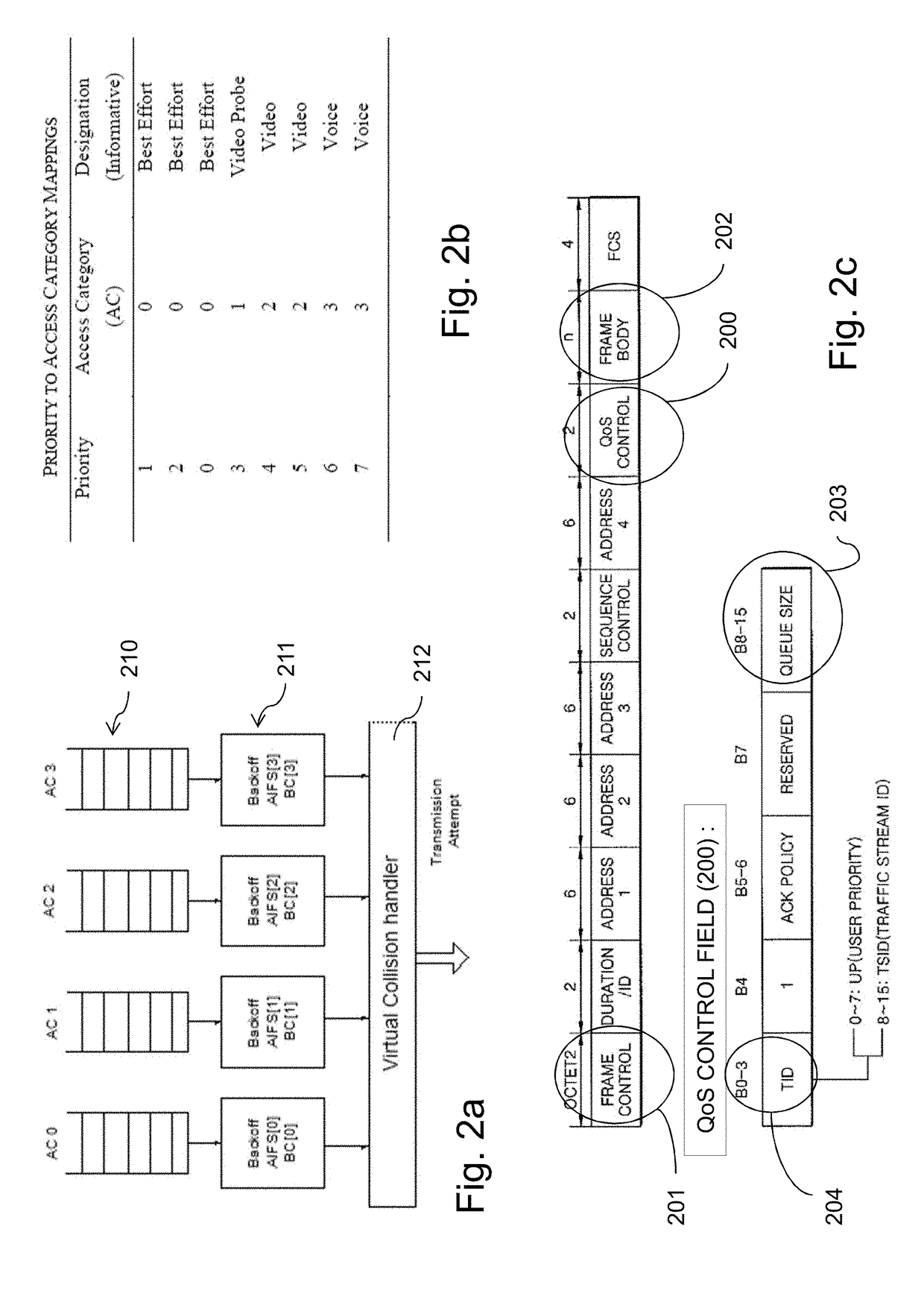
As one can note, buffer status knowledge has become the critical point for the access point, acting as the central control entity for MU UL allocation: if stations without expected amount of uplink packets are polled for uplink OFDMA transmission, allocated uplink resources are wasted leading to system throughput degradation.
However, there are situations where the current version of buffer size reporting according to the 802.11 standard is not satisfactory, and conducting the access point to faulty allocate, to one or the other of these several stations, the resource units over which MU UL communications may take place.

Method used


Image

  • Method and apparatus for reporting quantity of data to be transmitted in a wireless network
  • Method and apparatus for reporting quantity of data to be transmitted in a wireless network
  • Method and apparatus for reporting quantity of data to be transmitted in a wireless network

Examples


Embodiment Construction

[0072]The invention will now be described by means of specific non-limiting exemplary embodiments and by reference to the figures.

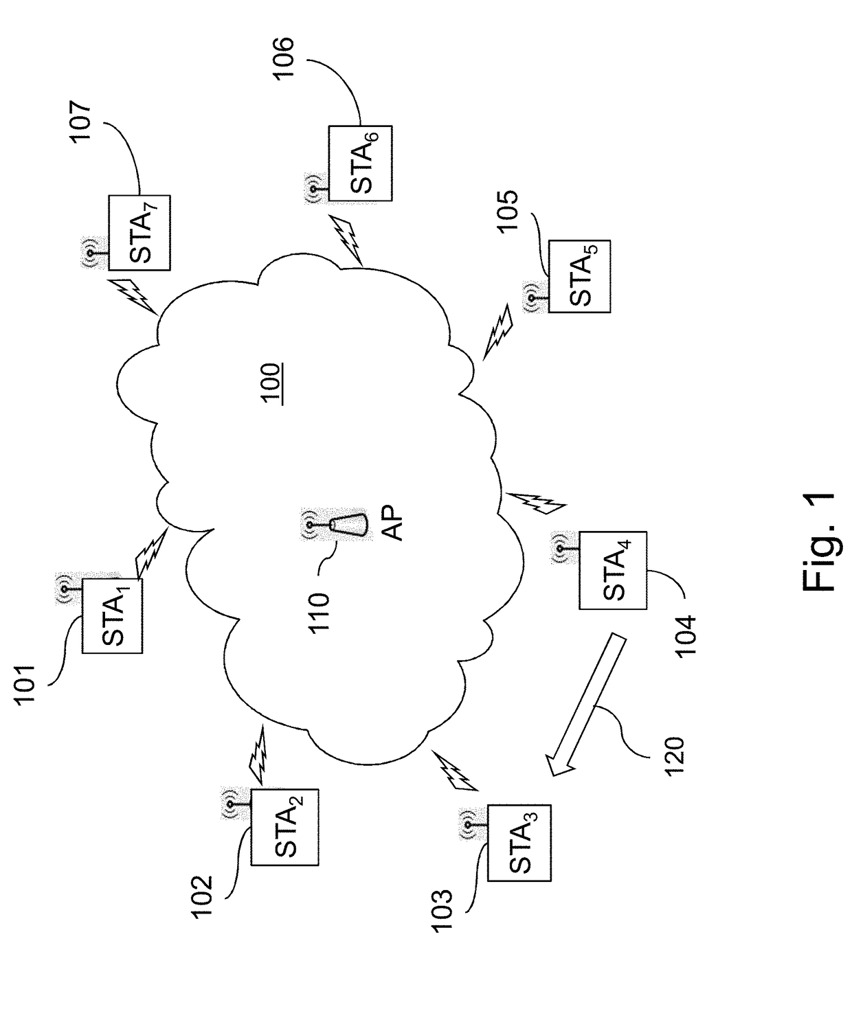
[0073]FIG. 1 illustrates a communication system in which several communication stations 101-107 exchange data frames over a radio transmission channel 100 of a wireless local area network (WLAN), under the management of a central station, or access point (AP) 110, also seen as a station of the network. The radio transmission channel 100 is defined by an operating frequency band constituted by a single channel or a plurality of channels forming a composite channel.

[0074]Access to the shared radio medium to send data frames is based on the CSMA / CA technique, for sensing the carrier and avoiding collision by separating concurrent transmissions in space and time. Carrier sensing in CSMA / CA is performed by both physical and virtual mechanisms. Virtual carrier sensing is achieved by transmitting control frames to reserve the medium prior to transmission of data...


PUM


Abstract

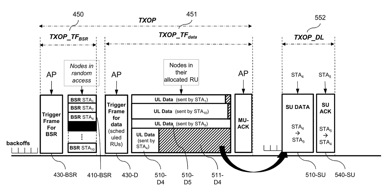
A method of communication in a wireless network comprising a plurality of wirelessly communicating stations, the method comprising by at least one emitting station having data to be directly transmitted to at least two different destination stations, generating a buffer status report to be transmitted to one of the destination stations, the buffer status report indicating an amount of data stored in at least an emission buffer of the emitting station, the emission buffers comprising all data to be transmitted to all the destination stations; transmitting the buffer status report to the destination station; wherein the amount of data is limited to the amount of data stored in at least an emission buffer of the emitting station to be transmitted to the destination station that will receive the buffer status report. Accordingly, scheduled traffic by a station is made with an accurate amount of data.

Description

PRIORITY CLAIM / INCORPORATION BY REFERENCE[0001]This application claims the benefit under 35 U.S.C. §119(a)-(d) of United Kingdom Patent Application No. 1612194.9, filed on Jul. 13, 2016 and entitled “METHOD AND APPARATUS FOR REPORTING QUANTITY OF DATA TO BE TRANSMITTED IN A WIRELESS NETWORK”. The above cited patent application is incorporated herein by reference in its entirety.FIELD OF THE INVENTION[0002]The present invention relates generally to communication networks and more specifically to wireless communication methods in wireless network comprising a plurality of stations, one of these stations playing the role of an access point, the other stations being connected to the access point, and corresponding devices.[0003]The invention finds application in wireless communication networks, in particular to the access of an 802.11ax composite channel and of OFDMA Resource Units forming for instance an 802.11ax composite channel for Uplink communication to the access point. One appli...

Claims


Application Information

Patent Timeline
IPC IPC(8): H04W28/02H04W92/10
CPCH04W92/10H04W28/0278H04W72/04
Inventor VIGER, PASCALBARON, STEPHANENEZOU, PATRICE
Owner CANON KK
Learn More