
Air cleaner

a technology of air cleaner and air filter, which is applied in the field of air cleaner, can solve the problems of air cleaners in the prior art that fail to completely control the dispersion of air contaminants in the outer environment, air cleaners in the prior art produce noise, etc., and achieve the effect of preventing or minimizing the effect and facilitating assembly

Active Publication Date: 2018-01-25
CURRENT WAYS
View PDF9 Cites 1 Cited by
  • Summary
  • Abstract
  • Description
  • Claims
  • Application Information

AI Technical Summary

Benefits of technology

This patent is about an ionizer and collector grid apparatus that helps reduce coronal discharge and audible noise. The frames of the ionizer and collector grid are suspended within the apparatus frame with isolating members made of a non-arc tracking material. The ionizer and collector grids may also be shaped to have no sharp or jagged edges to further minimize coronal discharge and audible noise. The high voltage power supply has output over-current protection to prevent unwanted high voltage tracking and detect undesired contacts with a user, indicating a replacement of an internal component is required. The high voltage power supply, rear filter, and front filter are provided as modular components for easy assembly and disassembly in the air cleaner.

Problems solved by technology

Air cleaners in the prior art, however, fail to completely control the dispersion of air contaminants in the outer environment by allowing some of the contaminants to escape and either remain suspended in the air or adhere to walls and ceilings.
Moreover, air cleaners in the prior art produce noise, even when air movement is powered electro-kinetically, without the use of fans.

Method used


Image

  • Air cleaner
  • Air cleaner
  • Air cleaner

Examples


Embodiment Construction

[0017]The following description relates to an embodiment of the invention. It should be understood, however, that the concepts described herein can be applied to a variety of other embodiments and, accordingly, the present description is not intended to limit the invention in any way.

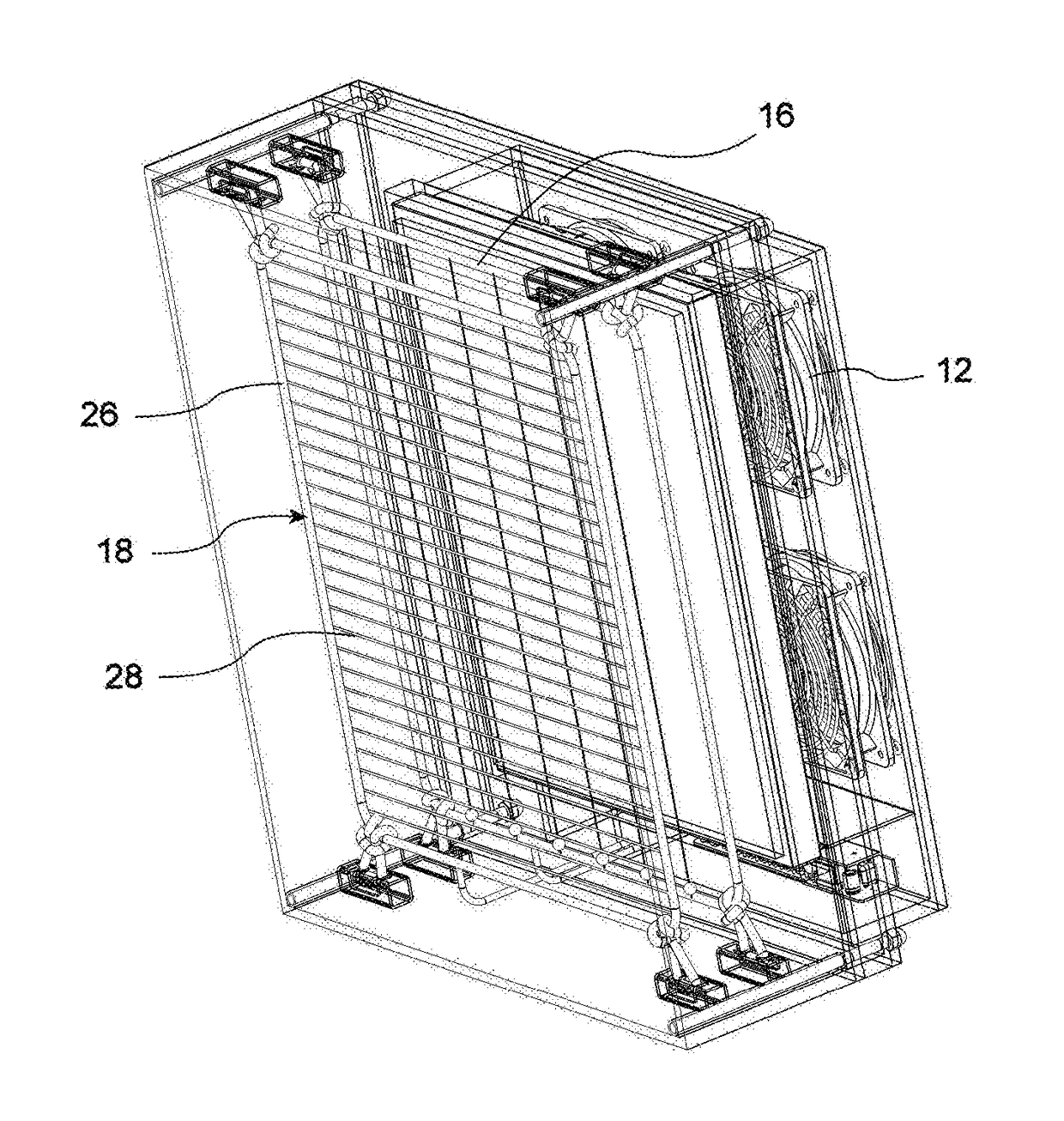
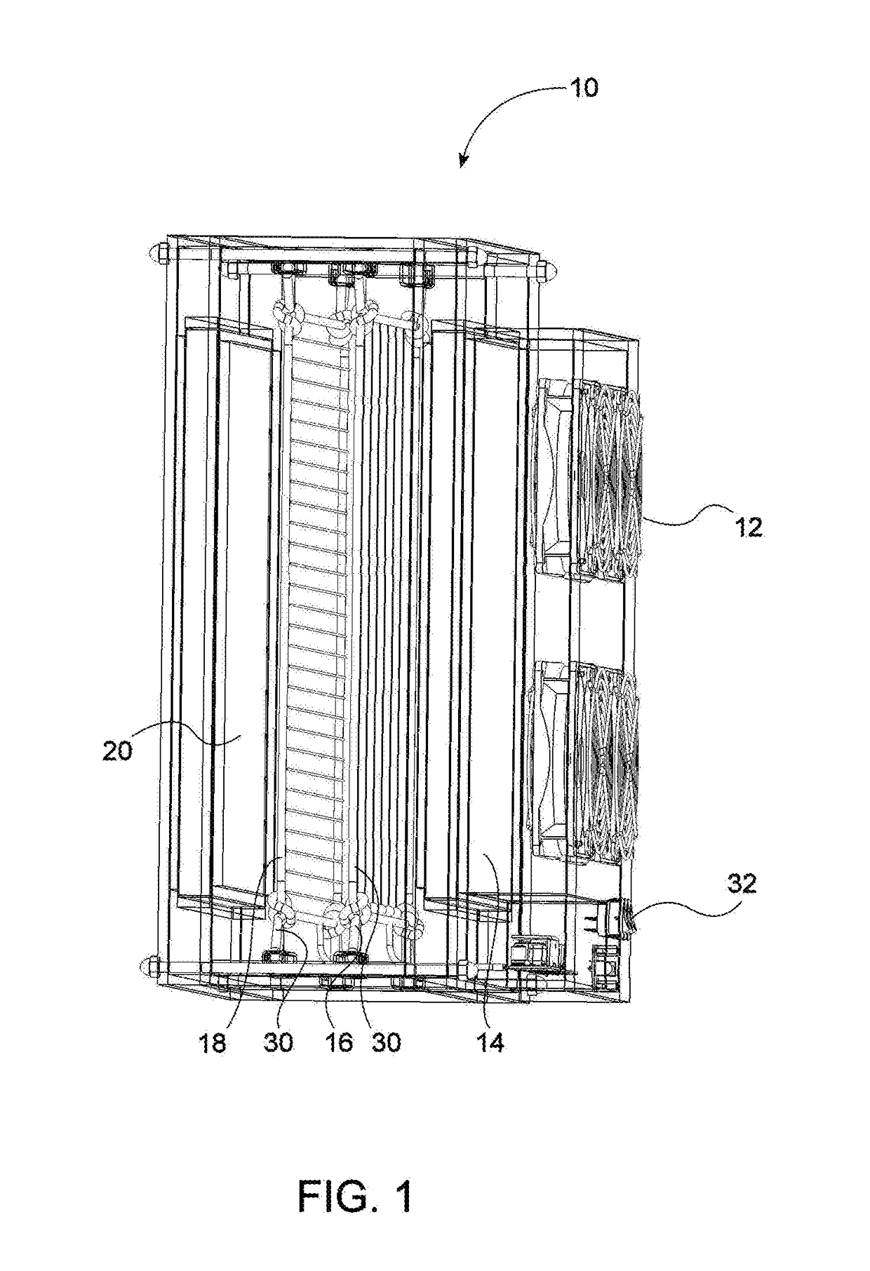
[0018]Referring first to FIG. 1, an air cleaner, or air purifier, 10 according to the invention includes a plurality of fans 12 in the rear area, a rear filter 14, an ionizer grid 16, a collector grid 18 and a front filter 20.

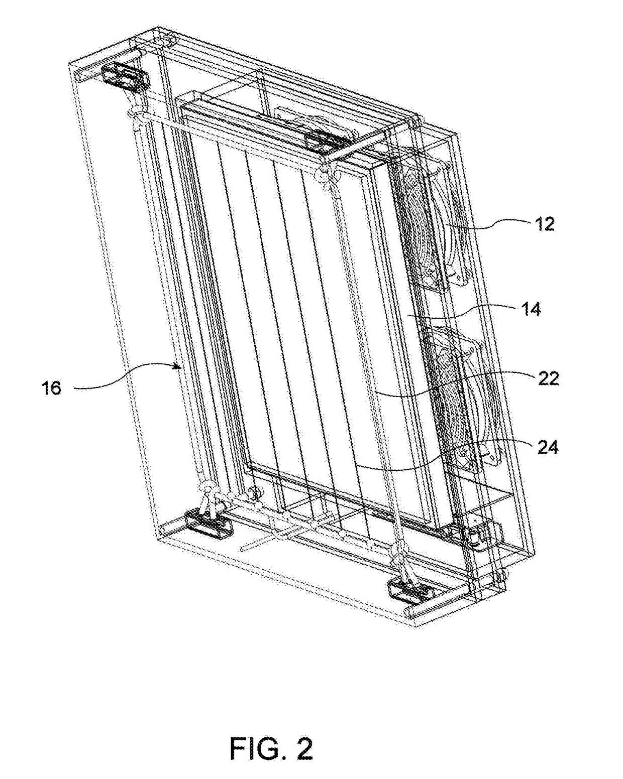
[0019]FIG. 2 illustrates a vertical cross-section of air cleaner 10 showing ionizer grid 16 in the forefront. Ionizer grid 16 is shaped has a frame 22 with a plurality of parallel wires 24 that extend between opposite sides of frame 22. In the illustrated embodiment, wires 24 extend in a vertical direction, but in different embodiments of the invention wires 24 may extend in different directions. In one embodiment, wires 24 have a diameter of 0.006″ (0.15 mm).

[0020]A high voltage p...


PUM

PropertyMeasurementUnit
Electric potential / voltageaaaaaaaaaa
Speedaaaaaaaaaa

Abstract

An air cleaner includes a rear filter receiving air from the outer environment, an ionizer grid connected to a high voltage power supply and having wires extending between opposite sides of a frame such to emit positively charged ions and apply an electrostatic charge on the air received from the rear filter; a collector grid connected to ground and having wires extending between opposite sides of a frame, the combination of the ionizer and collector grids causing the air to move toward the collector grid; a front filter collecting contaminants suspended in the air received from the collector grid; and an apparatus frame housing the rear filter, the ionizer and collector grids, and the front filter, wherein the frames of the ionizer and collector grids are suspended within the apparatus frame with isolating members made of a non-arc tracking material, such to minimize coronal discharge and reduce audible noise.

Description

FIELD OF THE INVENTION[0001]The present invention relates to an air cleaner that uses an ionizing system to accelerate air movement through the system and remove essentially all airborne pollutants. An air cleaner according to the invention generates very low noise and can be constructed to process different amounts of air. In one application, an air cleaner according to the invention can be used to clean the air of a typical bedroom.BACKGROUND OF THE INVENTION[0002]An air cleaner is a device that uses electrical voltage of positive polarity to ionize, or electrically charge, air molecules, which are causes to adhere to a collector member. Most commercial air cleaners are designed to generate negative ions, which are de-ionized by seeking electrodes of opposite polarity or earthed conductors, such as walls and ceilings.[0003]Air cleaners in the prior art are disclosed, for example, in U.S. Pat. No. 3,744,217 to Ebert, U.S. Pat. No. 3,747,300 to Knudson, U.S. Pat. No. 3,999,964 to Ca...

Claims


Application Information

Patent Timeline
IPC IPC(8): B03C3/86B03C3/019B03C3/09B03C3/41B03C3/36H01T23/00B03C3/74B01D53/86F24F13/28F24F13/24F24F3/16B03C3/011B03C3/47F24F8/108F24F8/167F24F8/98
CPCB03C3/86B03C3/011B03C3/019B03C3/09B03C3/41B03C3/368B03C3/47B03C3/743B01D53/8675F24F13/28F24F13/24F24F3/1603H01T23/00B03C2201/04B01D2255/2073B01D2255/20761B01D2257/106F24F2003/1682B03C3/70H01T19/00B03C3/12B03C3/155B03C2201/14B03C2201/28F24F8/30F24F8/108F24F8/98F24F8/167
Inventor CARROLL, SCOTTWING, KENNETH
Owner CURRENT WAYS
Learn More