Imaging apparatus, imaging apparatus body, and method of controlling imaging apparatus

a technology of imaging apparatus and body, which is applied in the direction of exposure control, camera filters, instruments, etc., can solve the problems of flickering, user's operation relating to the switching of the program diagram, and the user's switching to the second program diagram, so as to reduce the occurrence of blurring and increase the range

Active Publication Date: 2018-01-25
FUJIFILM CORP
View PDF6 Cites 9 Cited by
  • Summary
  • Abstract
  • Description
  • Claims
  • Application Information

AI Technical Summary

Benefits of technology

[0012]The present invention has an object to provide an imaging apparatus capable of increasing a range in which an open aperture value is set to be available through a neutral density filter and reducing occurrence of blurring, an imaging apparatus body, and a method of controlling the imaging apparatus.
[0027]According to the present invention, in the case where the apodization filter is disposed on the optical path, an exposure value may be greater than the specific amount of exposure (may exceed a region in which the aperture value is fixed at the open aperture value). In this case, the neutral density filter is inserted in the optical path. Therefore, it is possible to increase a range in which the open aperture value is set to be available through the neutral density filter, and it is possible to reduce occurrence of blurring.

Problems solved by technology

In a case where the imaging shutter speed is increased, there is a concern about a problem such as flickering.
However, in the imaging apparatus, in accordance with insertion and removal of the APD filter, switching to the second program diagram is not performed.
Thus, in cases of inserting and removing the APD filter, there is a problem in that a user has to perform operations relating to the switching of the program diagrams.
Therefore, there is a problem in that blurring tends to occur due to the insertion of the APD filter and the insertion of the neutral density filter.
This problem is worse as the imaging shutter speed is slower.
This problem occurs not only in a case of the imaging apparatus in which the APD filter is inserted into or removed from the optical path, but also in a case of the imaging apparatus in which the APD filter is disposed on the optical path and only a program diagram for APD is used.

Method used


Image

  • Imaging apparatus, imaging apparatus body, and method of controlling imaging apparatus
  • Imaging apparatus, imaging apparatus body, and method of controlling imaging apparatus
  • Imaging apparatus, imaging apparatus body, and method of controlling imaging apparatus

Examples


first embodiment

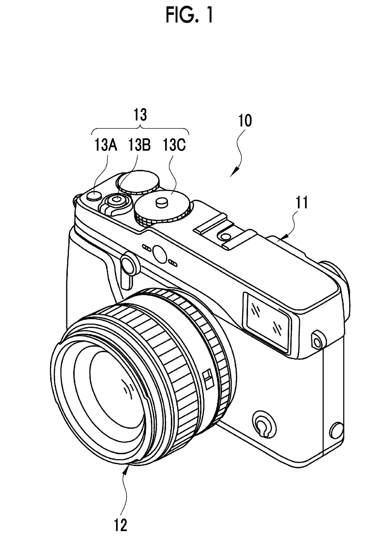
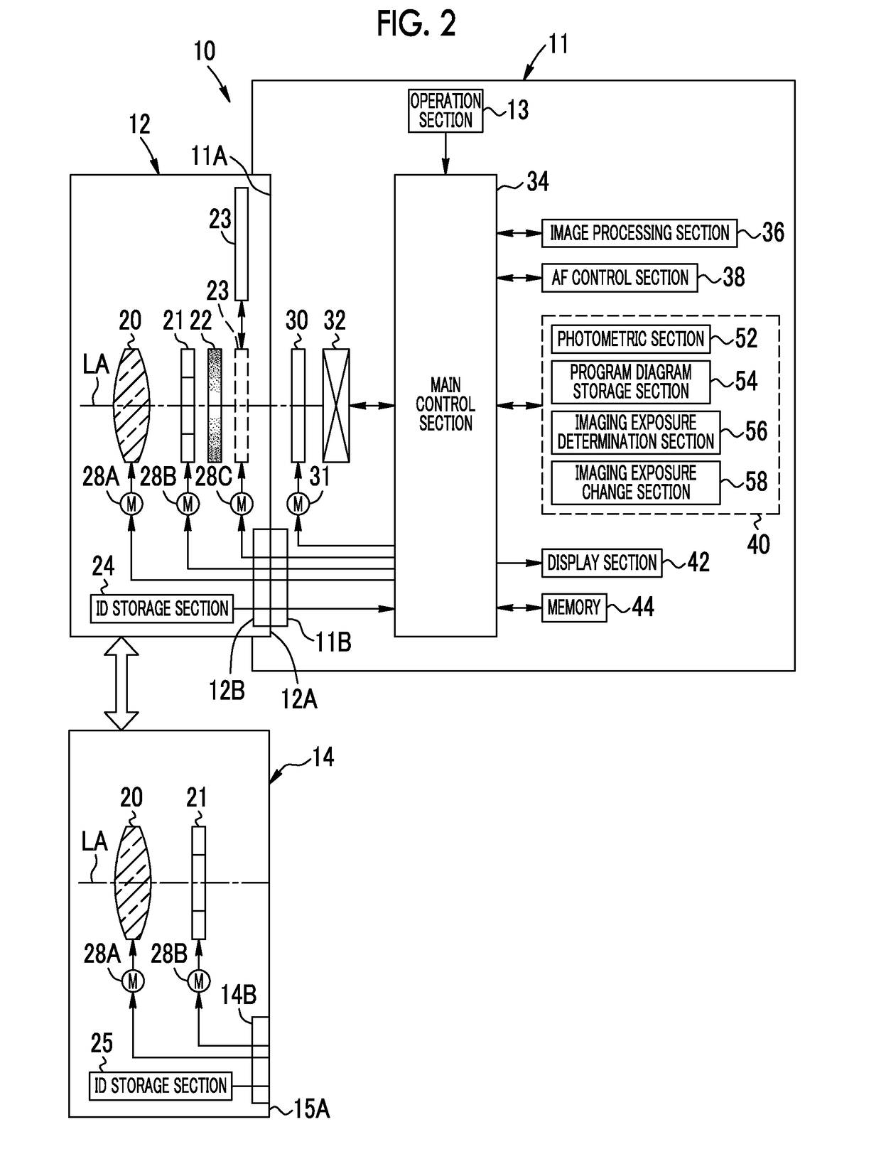
[0043]In FIG. 1, the imaging apparatus 10 of the present invention is an interchangeable lens type digital camera, and comprises an imaging apparatus body 11 and a first lens barrel 12 which is detachably mounted on the imaging apparatus body 11. The first lens barrel 12 is a lens barrel which has an apodization (APD) filter 22 (refer to FIG. 2).

[0044]In the imaging apparatus body 11, an operation section 13 is provided. The operation section 13 includes a power button 13A, a shutter button 13B, a mode switch dial 13C, and the like. The power button 13A operates in a case where power of the imaging apparatus 10 is turned on / off.

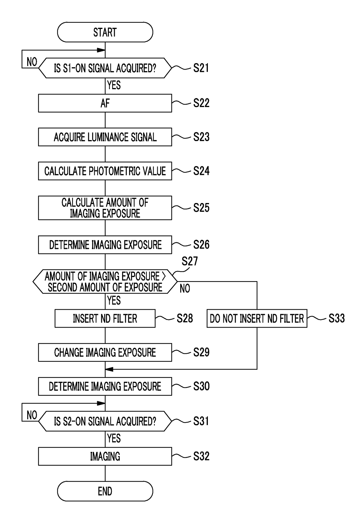
[0045]The shutter button 13B is a two-stage-stroke-type switch which is capable of so-called “half pressing” and “full pressing”. The shutter button 13B outputs an S1-on signal through half pressing, and outputs an S2-on signal through full pressing which is more pressed than half pressing. The imaging apparatus 10 performs imaging preparation processing such...

second embodiment

[0092]In the first embodiment, as the operation modes of the imaging apparatus 10, a still image capturing mode and a reproduction mode are provided. However, in a second embodiment, a moving image capturing mode is provided. The moving image capturing mode can be switched by the mode switch dial 13C. In the moving image capturing mode, moving image capturing is performed by fully pressing the shutter button 13B during live view display. Hereinafter, the moving image capturing mode will be described.

[0093]The imaging element 32 performs an imaging operation in a rolling shutter system. As shown in FIG. 11, the imaging element 32 performs resetting of electric charge, exposure, and reading of accumulated electric charge, for each pixel row. Therefore, the exposure time period differs for each pixel row. In a case of moving image capturing mode, resetting and reading operations from the first pixel row to the last pixel row are repeatedly performed.

[0094]In FIG. 12, in a second progra...

third embodiment

[0101]In the first embodiment, in a case where the amount of imaging exposure EVa is greater than the second amount of exposure EV2, the ND filter 23 is immediately inserted in the optical path. However, in the third embodiment, the amount of imaging exposure EVa may be equal to or greater than the third amount of exposure EV3 greater than the second amount of exposure EV2. In this case, the ND filter 23 is inserted in the optical path.

[0102]In FIG. 13, in the second program diagram P22 of the third embodiment, in a region where the amount of exposure EV is equal to or less than the second amount of exposure EV2, the aperture value is fixed at the open aperture value Fmin, and thus EV2=14. The shutter speed corresponding to the second amount of exposure EV2 is set as the limit speed on the high speed side of the shutter unit 30, in a manner similar to that of the first embodiment. In a manner similar to that of the first embodiment, the second program diagram P22 is used in a case w...


PUM


Abstract

The imaging apparatus includes a stop, an APD filter, a ND filter, an imaging element, a main control section, a photometric section, a program diagram storage section, and an imaging exposure determination section. The ND filter can be inserted into or removed from the optical path. The photometric section calculates a photometric value from an imaging signal which is obtained by the imaging element. The program diagram storage section stores a program diagram in which an aperture value is fixed at an open aperture value at a specific amount of exposure or less. The imaging exposure determination section determines imaging exposure on the basis of an amount of imaging exposure which is calculated from photometric value and the program diagram. The main control section inserts the ND filter in the optical path in a case where the amount of imaging exposure is greater than the specific amount of exposure.

Description

CROSS-REFERENCE TO RELATED APPLICATIONS[0001]This application is a Continuation of PCT International Application No. PCT / JP2016 / 057216 filed on Mar. 8, 2016, which claims priority under 35 U.S.C § 119(a) to Japanese Patent Application No. 2015-069483 filed on Mar. 30, 2015. The above application is hereby expressly incorporated by reference, in its entirety, into the present application.BACKGROUND OF THE INVENTION1. Field of the Invention[0002]The present invention relates to an imaging apparatus comprising an apodization filter, an imaging apparatus body, and a method of controlling the imaging apparatus.2. Description of the Related Art[0003]In the past, there are known imaging apparatuses comprising apodization filters (hereinafter referred to as an APD filter) (refer to JP2005-62733A (corresponding to US2005 / 0041949A1)). The APD filter has an optical characteristic that light transmittance is lower at a position farther from the optical axis. Consequently, a dimming effect obtai...

Claims


Application Information

Patent Timeline
Patent Type & Authority Applications(United States)
IPC IPC(8): H04N5/238H04N5/232H04N5/225
CPCH04N5/238H04N5/2254H04N5/23232G03B7/097G03B7/18G03B11/00H04N23/60H04N23/667H04N23/75H04N23/71H04N23/73H04N23/951H04N23/72
Inventor UCHIDA, AKIHIRO
Owner FUJIFILM CORP
Why Eureka
Try Eureka