Aerobraking satellite deorbiting system

Active Publication Date: 2018-02-01
ARIANE GRP SAS
View PDF0 Cites 3 Cited by
  • Summary
  • Abstract
  • Description
  • Claims
  • Application Information

AI Technical Summary

Benefits of technology

[0022]The presently disclosed embodiment aims to propose a simple and low energy cost solution because of the little mass that it adds to make it possible to quarantee deorbiting over a controlled period of a satellite that is at its end of life or is to be deactivated. The presently

Problems solved by technology

At present no satellite is able to meet this requirement without carrying on board a dedicated deorbiting system of high mass or without using a large fraction (approximately 30%) of the onboard hydrazine to move the satellite into deorbiting position.
In fact, after its operational life, a satellite is no longer maintained under control by its operator: the satellite generally then begins to rotate on itself because of the effect of various forces that vary in time: aerodynamic drag, solar wind, magnetic field, variable gravitational field; the satellite no longer has a stable attitude in its orbit and the aerobraking structure can no longer be oriented optimally relat

Method used


Image

  • Aerobraking satellite deorbiting system
  • Aerobraking satellite deorbiting system
  • Aerobraking satellite deorbiting system

Examples


Example

[0055]The principle of the disclosed embodiment consists in equipping a satellite with a deorbiting system that is deployed at the satellite end of life and combines a deorbiting sail and a gravity gradient device to maintain said sail in a position generating a high drag adapted to brake the satellite and therefore to cause it to lose altitude.

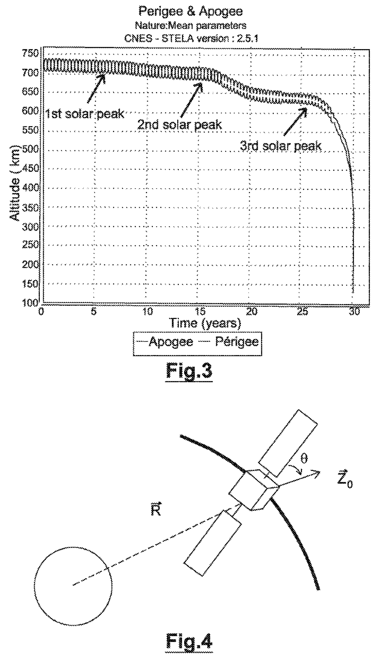
[0056]The device stabilizes the satellite at end of life by means of the gravity gradient device, the sail and the gravity gradient device being designed so that the sail is the most perpendicular to the trajectory despite the flipping torque caused by drag. The disclosed embodiment also has the object of designing the sail and the gravity gradient device so that the denser the residual atmosphere the more the sail departs from this perpendicular position but remains within the stable range of the system.

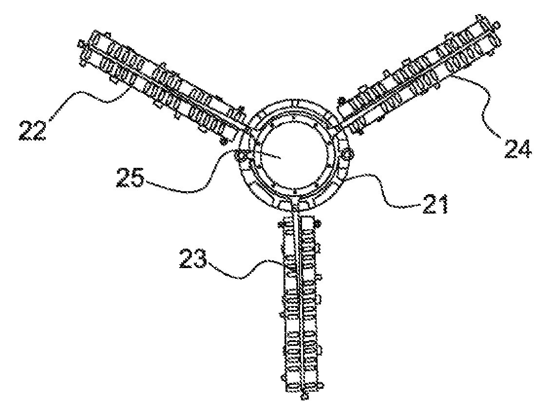
[0057]The gravity gradient device more particularly consists of a mast fixed to the satellite and a remote mass at the opposite end of the m...


PUM


Abstract

A satellite deorbiting device including an aerobraking surface including a satellite attitude control device with gravity gradient, the device with gravity gradient including at least one mast carrying the aerobraking surface, a first end of which is secured to the satellite and the second end of which is provided with a mass, such that the mast is oriented in a direction opposing that of the planet around which the satellite orbits.

Description

CROSS REFERENCE TO RELATED APPLICATIONS[0001]This application is the National Stage of International Application No. PCT / EP2016 / 052173, having an International Filing Date of 2 Feb. 2016, which designated the United States of America, and which International Application was published under PCT Article 21(2) as WO Publication No. 2016 / 124591 A1, and which claims priority from and the benefit of French Application No. 1550829, filed 3 Feb. 2015, the disclosures of which are incorporated herein by reference in their entireties.BACKGROUND1. Field[0002]The presently disclosed embodiment is situated in the field of aerobraking structures for deorbiting satellites and provides a system for this purpose.[0003]In the satellite field there exist more and more regulations or rules of good practice that require operators to eliminate their satellites from their orbit after their end of operational life, planned or accidental end of life.[0004]The presently disclosed embodiment concerns more par...

Claims


Application Information

Patent Timeline
IPC IPC(8): B64G1/62B64G1/10B64G1/24B64G1/22B64G1/34
CPCB64G1/62B64G1/222B64G1/34B64G1/242B64G1/10
Inventor RASSE, BENJAMINDAMIANO, PATRICE
Owner ARIANE GRP SAS
Why Eureka
Try Eureka