

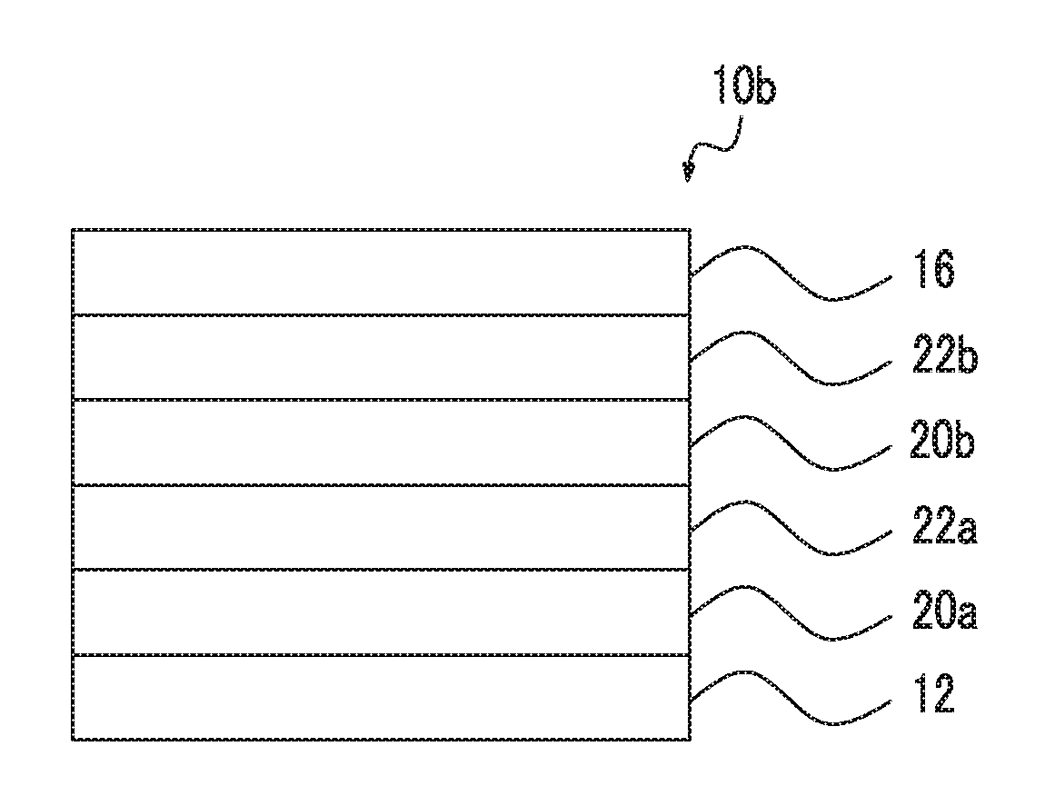
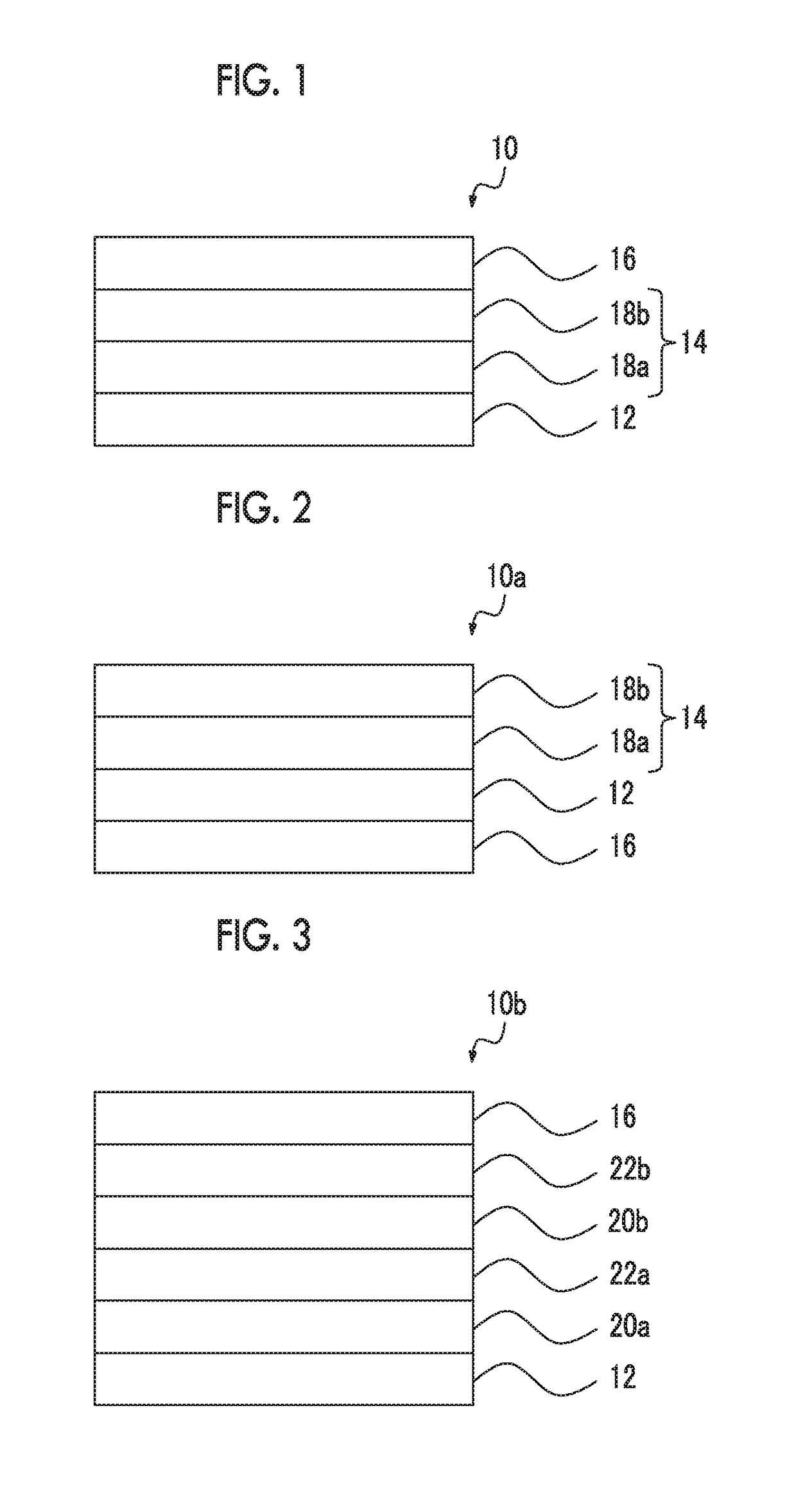
Composition kit, laminate and method for producing same, and bandpass filter
a bandpass filter and laminate technology, applied in the field of composition kits, can solve the problems of time and effort required to prepare laminates, and the cost of production, and achieve the effects of reducing angle dependence, reducing angle dependence, and facilitating production of bandpass filters
- Summary
- Abstract
- Description
- Claims
- Application Information
AI Technical Summary
Benefits of technology
Problems solved by technology
Method used
Image


Examples
example 1
Filter A
[0681]According to the procedure for preparing the laminate (A) () and the procedure for preparing an infrared transmitting film A (Preparation of infrared transmitting film A), the laminate (A) and the infrared transmitting film A were formed on a substrate to prepare a bandpass filter A.
[0682]The transmittance of the bandpass filter A in the wavelength range of 400 to 1100 nm was measured using a spectrophotometer (ref. glass substrate) of a UV-VIS-near IR spectrophotometer (U-4100 manufactured by Hitachi High-Technologies Corporation). The results are shown in FIG. 11.
example 2
Filter B
[0683]According to the procedure for preparing the laminate (B) () and the procedure for preparing an infrared transmitting film B (Preparation of infrared transmitting film B), the laminate (B) and the infrared transmitting film B were formed in on a substrate to prepare a bandpass filter B.
[0684]The transmittance of the bandpass filter B in the wavelength range of 400 to 1100 nm was measured using a spectrophotometer (ref. glass substrate) of a UV-VIS-near IR spectrophotometer (U-4100 manufactured by Hitachi High-Technologies Corporation). The results are shown in FIG. 12.
example 3
Filter C
[0685]According to the procedure for preparing the laminate (C) () and the procedure for preparing an infrared transmitting film C (Preparation of infrared transmitting film C), the laminate (C) and the infrared transmitting film C were formed on a substrate to prepare a bandpass filter C.
[0686]The transmittance of the bandpass filter C in the wavelength range of 400 to 1100 nm was measured using a spectrophotometer (ref glass substrate) of a UV-VIS-near IR spectrophotometer (U-4100 manufactured by Hitachi High-Technologies Corporation). The results are shown in FIG. 13.
PUM
| Property | Measurement | Unit |
|---|---|---|
| helical twisting power | aaaaa | aaaaa |
| haze | aaaaa | aaaaa |
| wavelength range | aaaaa | aaaaa |
Abstract
Description
Claims
Application Information