Engine system

a technology of engine and system, applied in the direction of machines/engines, electrical control, exhaust treatment electric control, etc., can solve the problems of deteriorating control performance to control the correct egr rate in a transitional period, increasing the error of an egr ratio,

Active Publication Date: 2018-02-01
HYUNDAI MOTOR CO LTD
View PDF7 Cites 16 Cited by
  • Summary
  • Abstract
  • Description
  • Claims
  • Application Information

AI Technical Summary

Benefits of technology

[0017]Various aspects of the present invention are directed to provi

Problems solved by technology

Accordingly, a time delay is generated when controlling the recirculation gas amount supplied to the combustion chamber such that there is a problem that an error of an EGR ratio is increased.
Also, bec

Method used


Image

  • Engine system
  • Engine system
  • Engine system

Examples


Embodiment Construction

[0040]Reference will now be made in detail to various embodiments of the present invention(s), examples of which are illustrated in the accompanying drawings and described below. While the invention(s) will be described in conjunction with exemplary embodiments, it will be understood that the present description is not intended to limit the invention(s) to those exemplary embodiments. On the contrary, the invention(s) is / are intended to cover not only the exemplary embodiments, but also various alternatives, modifications, equivalents and other embodiments, which may be included within the spirit and scope of the invention as defined by the appended claims.

[0041]The drawings and description are to be regarded as illustrative in nature and not restrictive. Like reference numerals designate like elements throughout the specification.

[0042]Further, in the drawings, the sizes and thicknesses of the components are exemplarily provided for convenience of description, but the present inven...


PUM


Abstract

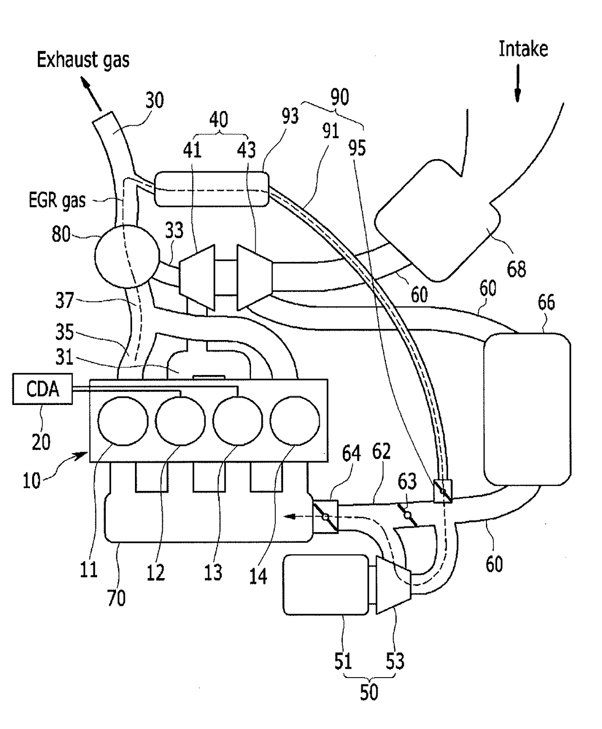
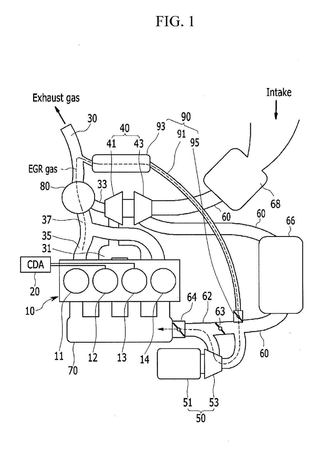
An engine system may include an engine having an intake line flowing an intake gas supplied to the combustion chambers; an intake manifold; a throttle valve provided at a front of the intake manifold and controlling an air amount supplied to the combustion chamber; an electric supercharger provided at the throttle valve and including a motor and an electric compressor operated by the motor to supply the supercharged air to the combustion chamber; an exhaust gas processing device purifying an exhaust gas generated in the combustion chamber; and an exhaust gas recirculation device including a recirculation line branched from the downstream portion of the exhaust gas processing device and joined to the intake line of the upstream portion of the electric compressor, an EGR cooler mounted at the recirculation line, and an EGR valve mounted at a part where the recirculation line and the intake line are joined.

Description

CROSS-REFERENCE TO RELATED APPLICATION[0001]The present application claims priority to Korean Patent Application No. 10-2016-0094742 filed on Jul. 26, 2016, the entire contents of which is incorporated herein for all purposes by this reference.BACKGROUND OF THE INVENTIONField of the Invention[0002]The present invention relates to an engine system. More particularly, the present invention relates to an engine system minimizing an exhaust gas recirculation path.Description of Related Art[0003]An engine of a vehicle combusts a mixture of air inflowing from the outside and a fuel with an appropriate ratio to generate power.[0004]In a process of generating the power by driving the engine, the external air for the combustion must be appropriately supplied to obtain a desired output and combustion efficiency. For this, a turbocharger as a device for turbocharging the air for the combustion to increase the combustion efficiency of the engine is used.[0005]In general, a turbocharger is a dev...

Claims


Application Information

Patent Timeline
IPC IPC(8): F02M26/08F02B37/04F02M26/22F02D9/02F02M26/15F02M26/17F02D41/00F02B37/16
CPCF02M26/08F02D41/0087F02B37/04F02B37/16F02D9/02F02M26/15F02M26/17F02M26/22F02B75/18F02B2075/1816F02D17/02F02D2700/056F01N13/107F01N2340/06F02B37/162F02B37/183F02B39/10F02D41/0007Y02T10/12F01N9/00F02D9/08F02D13/06F02M26/51
Inventor LEE, JOOWONPARK, JONG IICHOI, KWANHEELEE, HYUNGBOKHAN, DONG HEELIM, HYUN JUN
Owner HYUNDAI MOTOR CO LTD
Why Eureka
Try Eureka