Bearing arrangement

a bearing and arrangement technology, applied in the direction of bearing rigid support, sliding contact bearing, machine/engine, etc., can solve the problems of high degree of precision, damage to one or more bearings and the raceway, and the ball or roller of such bearings must be machined to a very high degree of precision

Active Publication Date: 2018-02-01
SIEMENS GAMESA RENEWABLE ENERGY AS
View PDF3 Cites 9 Cited by
  • Summary
  • Abstract
  • Description
  • Claims
  • Application Information

AI Technical Summary

Benefits of technology

[0009]An advantage of the bearing arrangement according to embodiments of the invention is that the bearing pads are distributed in an optimal manner around the drive shaft to provide support exactly where it is needed. In this way, the drive shaft is always optimally supported under all loading conditions.
[0011]An advantage of the bearing arrangement according to embodiments of the invention is that a main bearing that supports the drive shaft can be designed using a relatively economical fluid bearing or sliding bearing, while the wear on the bearing pads can be favourably minimized. In this way, the construction costs and maintenance costs can be reduced.
[0020]Loading on the drive shaft of such a wind turbine generally manifests as a downward force on the front-end of the drive shaft and an upward force on the back-end of the drive shaft. Therefore, in a particularly preferred embodiment of the invention, the front-end main bearing comprises a greater number of bearing pads in its lower half, and the back-end main bearing comprises a greater number of bearing pads in its upper half. In this way, the uneven loading on the drive shaft can be optimally counteracted by the main bearings at either end. Of course, alternative embodiment are equally possible, with an even distribution of pads on the downwind side and an uneven distribution of pads on the upwind side; or an even distribution of pads on the upwind side and an uneven distribution of pads on the downwind side.
[0022]In a preferred embodiment of the inventive bearing arrangement, at least one bearing is equipped with a pressure application means that is realized to apply pressure to a bearing pad in order to press the bearing pad's contact surface against the outer surface of the drive shaft. In one preferred embodiment, the pressure application means comprises at least one spring-loaded component arranged between the housing and a bearing pad. For example, a pair of springs arranged one on each side of the bearing liner may effectively press the curved contact surface against the drive shaft, even when the drive shaft is subject to axial forces originating from the rotor. In an alternative realization, a pressure application means can comprise an actuator that is driven by a hydraulic motor or a linear motor. In either case, a pressure application means can be realised to press the pad against the shaft surface by applying pressure, or to or pull the pad towards the housing (away from the drive shaft) by reducing the applied pressure. The amount of pressure to be applied to or released from a pad can be adjusted as required in order to adjust the pad's freedom of movement.

Problems solved by technology

However, the balls or rollers of such bearings must be machined to a very high degree of precision, and are generally very expensive.
Wear and tear can result in damage to one or more bearings and the raceways.
To replace a damaged part (roller or ball), it is generally necessary to dismantle the entire cage or race containing the moving parts, so that repair and replacement procedures are generally expensive.
However, it is problematic to distribute and design the pads of the fluid or sliding bearings in such a way that wear and maintenance costs are minimized.
However, in the case of a fluid bearing or a sliding bearing, such a design involves a relatively large number of bearing pads, resulting in higher costs.
A large number of pads also leads to increased power loss, a greater “out of tolerance” risk that can lead to an overloaded pad that is slightly too thick, a greater risk of pad failure, etc.
However, particularly in the case of a large wind turbine generator, the back-end bearing may be subject to significant loading even if the front-end main bearing has been designed to withstand maximum loading.

Method used


Image

  • Bearing arrangement
  • Bearing arrangement
  • Bearing arrangement

Examples


Embodiment Construction

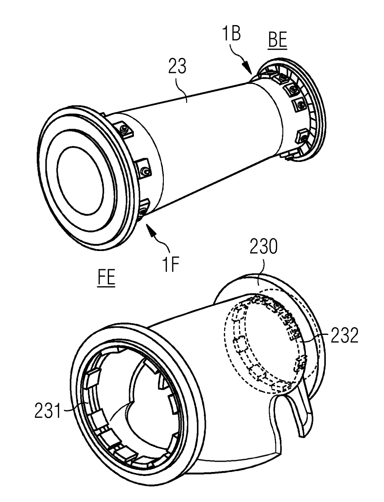
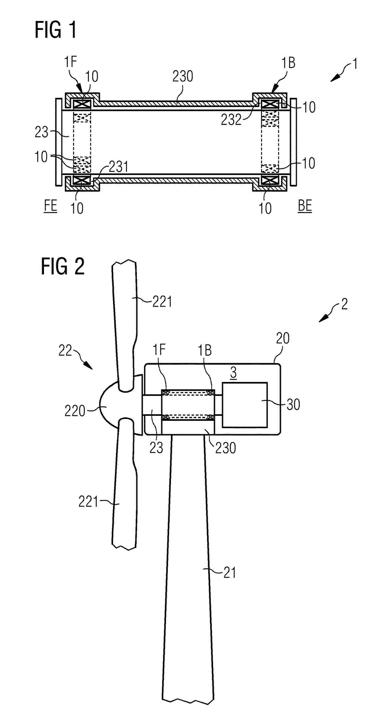
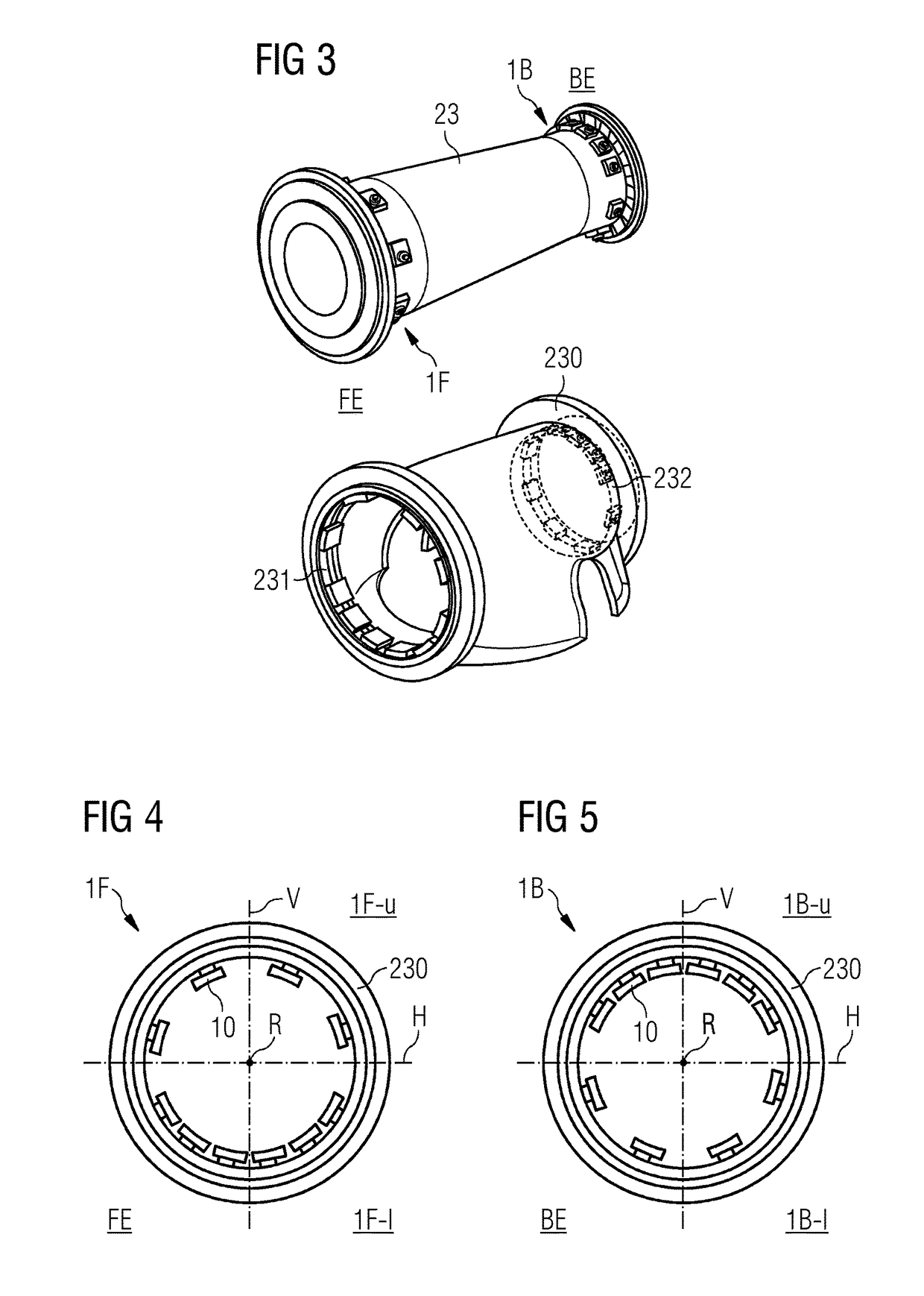
[0031]FIG. 1 shows a bearing arrangement 1 according to embodiments of the invention, used to support a drive shaft 23 in a drive shaft housing 230. The bearing arrangement 1 has a front-end bearing 1F in an annular space 231 at the front end FE of the drive shaft 23, and a back-end bearing 1B in an annular space 232 at the back end BE of the drive shaft 23. The diagram indicates an uneven distribution of bearing pads 10 at either end FE, BE.

[0032]FIG. 2 shows the bearing arrangement 1 of FIG. 1 installed to support a drive shaft 23 of a wind turbine generator 3. A wind turbine 2 comprises a nacelle 20 on top of a tower 21. A rotor 22 comprising a hub 220 and blades 221 mounted to the hub 22 will turn in response to an airflow over the blades 221. The rotor 22 is mounted to a drive shaft 23 to transfer the rotation to a generator rotor 30 (indicated in a simplified manner in the diagram) of the generator 3. The drive shaft 23 is held in place by a housing 230, and annular bearings 1...


PUM


Abstract

A bearing arrangement of an electrical machine is provided that includes a drive shaft extending through a housing, the bearing arrangement including a front-end bearing arranged about a front end of the drive shaft, and a back-end bearing arranged about an opposite end of the drive shaft, wherein a bearing includes a plurality of bearing pads arranged in an annular space between the drive shaft and the housing, and wherein at least one bearing includes an uneven distribution of bearing pads about the drive shaft. Furthermore, a wind turbine including such a bearing arrangement is also provided.

Description

CROSS-REFERENCE TO RELATED APPLICATION[0001]This application claims priority to European Application No. 16181950.3 having a filing date of Jul. 29, 2016, the entire contents of which are hereby incorporated by reference.FIELD OF TECHNOLOGY[0002]The following describes a bearing arrangement of an electrical machine, to support a drive shaft inside a housing. The following further describes a wind turbine comprising such a bearing arrangement.BACKGROUND[0003]A wind turbine generally comprises a nacelle mounted on top of a tower, and enclosing a generator. One type of generator is mounted to a drive shaft, which is turned by a rotor comprising a number of blades mounted to a hub at the upwind end of the nacelle. The rotor turns in response to an airflow over the blades. The drive shaft must be securely held in some way to ensure efficient transfer of the rotation to the generator. To this end, a drive shaft is usually held in place by a housing, with one or more main bearings between ...

Claims


Application Information

Patent Timeline
Patent Type & Authority Applications(United States)
IPC IPC(8): F03D80/70F16C17/02
CPCF03D80/70F16C17/02F16C2300/14F05B2240/53F16C2360/31F05B2240/60F16C17/246F16C17/26F16C35/02F16C2229/00F16C17/03F16C41/02F16C2300/32Y02E10/72
Inventor ERIKSEN, UFFELEMMA, EDOMTHOMSEN, KIMTHORHAUGE, MORTEN
Owner SIEMENS GAMESA RENEWABLE ENERGY AS
Why Eureka
Try Eureka