Feedwell having twisted plates

a technology of feedwell and plate, which is applied in the field of feedwells, can solve the problems of insufficient entrance energy or reduction of the velocity of the clarifier, the inability to efficiently recover from newly formed black liquor, and the inability to adequately disperse the entrance energy or reduce the velocity inside the clarifier, so as to improve the rate at which solids settle, reduce the entrance energy of the incoming feed, and improve the clarity of the removed liquid

Active Publication Date: 2018-02-08
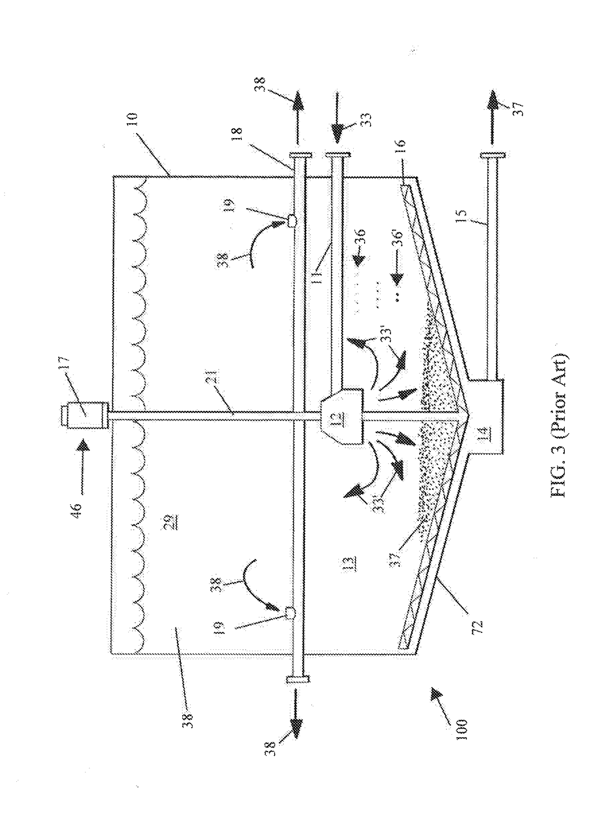
ANDRITZ INC
View PDF0 Cites 3 Cited by
  • Summary
  • Abstract
  • Description
  • Claims
  • Application Information

AI Technical Summary

Benefits of technology

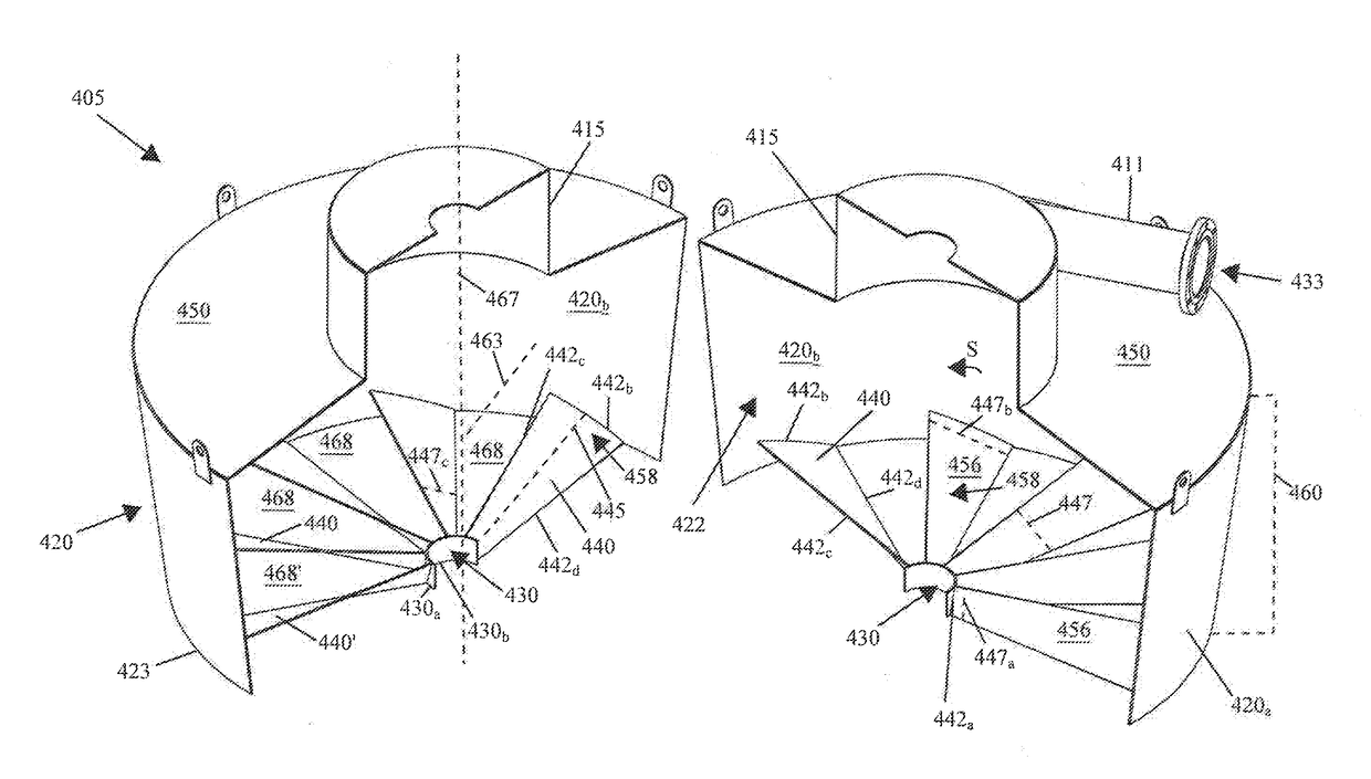
[0012]The problem of incomplete mixture separation in a clarifier is mitigated by using a feedwell in accordance with the present disclosure. Without being bounded by theory, the embodiments described herein may reduce the velocity of the feed slurry flow in the feedwell without increasing turbulence or shear force. In one exemplary embodiment, the feedwell may comprise twisted plates disposed at or near the bottom of the feedwell. The twisted plates may be disposed such that a leading face of the twisted plates is positioned to oppose the general direction of feed slurry movement in the feedwell. That is, the leading face can be configured to face the incoming feed slurry. An exemplary twisted plate may be twisted about a longitudinal axis extending from a first end to a second end, the second end being distally disposed from the first end. The first end of the twisted plate may engage a ring disposed within the feedwell, or near the bottom of the feedwell. In other exemplary embodiments, the ring may be absent. The second end of the twisted plate may extend toward an inner surface of a sidewall, wherein the sidewall may define the body of the feedwell. The center of the ring may be disposed coaxially with a vertical line extending though the feedwell. The first end of the twisted plate has a first slope as measured on a two-dimensional Cartesian plane. The first end of the twisted plate may engage the exterior surface of the ring at an initial angle, wherein the initial angle is the angle between the first end and a vertical line extending through the feedwell. The second end of the twisted plate can be longer than the first end. As a result, the surface area of the twisted plate's leading face may generally increase from the first end to the second end in embodiments in which the second end is longer than the first end. The leading face's surface area may be defined by the area between a first edge of the first end, a first edge of the second end, a first top edge of the top side, and a first bottom edge of the bottom side of the twisted plate, in which the twisted plate is configured to oppose the general flow direction of the feed slurry. The second end may have a final slope as measured on a two-dimensional Cartesian plane. The final slope may be shallower than the first slope. The height of the exemplary twisted plates can remain substantially constant while the volume of the twisted plates gradually increases from the first end to the second end. In other exemplary embodiments, the height of the twisted plates may increase or decrease from the first end to the second end. In still other exemplary embodiments, the surface area of the leading face of the twisted plates may remain substantially constant as measured from the first end to the second end of the twisted plates.
[0016]The embodiments described herein may be used with a flow of feed slurry to increase the rate at which solids settle out of the feed slurry, and thereby improve the clarity of the removed liquid.
[0017]It is further contemplated that the embodiments described herein may reduce the entrance energy of incoming feed slurry, without substantially increasing turbulence or shear force.
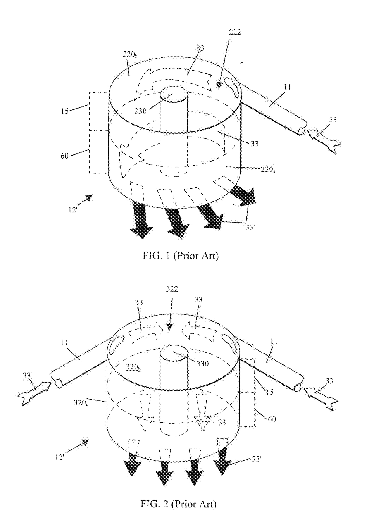
[0018]The embodiments disclosed herein may be used in the separation of liquid(s) and solid(s) from feed slurry materials or the like. In certain exemplary embodiments, a feedwell described herein may sufficiently dissipate the entrance energy of the total flow of the feed slurry (e.g., of the mixture of inlet liquid and solid materials) into a clarifier such that the total flow enters a settling zone as a plug flow. (e.g., such that the velocity of the feed slurry mixture is substantially constant across any cross-section of the area of the flow perpendicular to the axis of the flow). This reduced or substantially uniform or constant velocity may enable any solids in the feed slurry to settle out of the mixture more quickly or more easily than in situations where the velocity of the feed slurry entering the feedwell is inconsistent or too high. This improved “settling out” may in turn improve the clarity of the liquid that is ultimately separated or removed from the clarifier.

Problems solved by technology

While sodium hydroxide is reasonably abundant, the costs of producing pulp and paper would quickly become prohibitive if manufactures did not recover and recycle this chemical compound.
However, newly formed black liquor is generally too dilute for efficient chemical recovery.
However, these feedwell designs do not sufficiently dissipate the entrance energy or reduce the velocity inside the clarifier.
Further, even in cases where the velocity is reduced, turbulence and shear force may be increased.
Turbulence or shear force present in the clarifier may also have a detrimental effect on the ability of solids to settle out of the mixture.
Thus, in certain existing clarifier feedwells, the solids in the feed slurry may not sufficiently settle out, and the clarity of the separated or removed liquids (e.g., the clarified liquids) may suffer.

Method used


Image

  • Feedwell having twisted plates
  • Feedwell having twisted plates
  • Feedwell having twisted plates

Examples


Embodiment Construction

[0031]The following detailed description of the preferred embodiments is presented only for illustrative and descriptive purposes and is not intended to be exhaustive or to limit the scope and spirit of the invention. The embodiments were selected and described to best explain the principles of the invention and its practical application. One of ordinary skill in the art will recognize that many variations can be made to the invention disclosed in this specification without departing from the scope and spirit of the invention.

[0032]Similar reference characters indicate corresponding parts throughout the several views unless otherwise stated. Although the drawings represent embodiments of various features and components according to the present disclosure, the drawings are not necessarily to scale and certain features may be exaggerated in order to better illustrate embodiments of the present disclosure, and such exemplifications are not to be construed as limiting the scope of the p...


PUM

PropertyMeasurementUnit
offset angleaaaaaaaaaa

Abstract

A feedwell design for a clarifier that may better dissipate the entrance energy of feed slurry liquid exiting the feedwell and entering the clarifier. Plates having a surface area twisted around a longitudinal axis may be provided at the bottom of the feedwell. The plates may cause a change in the flow direction of the feed, from being mostly horizontal to mostly vertical, to slow the slurry. The provision of plates at the bottom of a feedwell in a clarifier may advantageously reduce the velocity of the materials entering the clarifier, or may increase the uniformity of the flow rate of the materials while reducing or maintaining the amount of shear force, turbulence, or other forces that may have a detrimental effect on clarification. Likewise, this may improve the rate at which solids settle out of the feed slurry solution, and thus improve the clarity of the removed liquid.

Description

CROSS-RELATED APPLICATION[0001]This application claims the benefit of U.S. Provisional Pat. App. No. 62 / 369,947 filed on Aug. 2, 2016, the entirety of which is incorporated herein by reference.BACKGROUND OF THE INVENTION1. Technical Field[0002]The present disclosure relates generally to clarifiers configured to separate lighter substances from heavier substances in the mineral processing, pulp and paper, water treatment, and waste treatment industries, and particularly to feedwells used in the mineral processing, pulp and paper, water treatment, and waste treatment industries.2. Related Art[0003]Facility operators use clarifiers in the pulp and paper industry and other industries to separate mixtures. Typically, the clarifier is a large holding tank or vessel. Operators pump fluid mixtures into the clarifier and allow gravity separation to occur. That is, if left undisturbed, suspended particles eventually settle out of the solution. Once sufficiently separated, operators may extrac...

Claims


Application Information

Patent Timeline
Patent Type & Authority Applications(United States)
IPC IPC(8): B01D21/24
CPCB01D21/2427B01D21/2411B01D21/0042B01D21/0087B01D21/06B01D21/08B01D21/2444
Inventor RAWLS, LINDSAY BRANDINO
Owner ANDRITZ INC
Why Eureka
Try Eureka