Layout setting method and layout setting apparatus

a layout setting and layout technology, applied in the direction of programmed manipulators, instruments, programme control, etc., can solve the problems of unevenness, a strut and ventilation duct in the room, and the like, and achieve the effect of preventing the robot arm from operating, preventing interference with the peripheral device, and preventing unevenness

Inactive Publication Date: 2018-02-08
CANON KK
View PDF20 Cites 18 Cited by
  • Summary
  • Abstract
  • Description
  • Claims
  • Application Information

AI Technical Summary

Problems solved by technology

Besides, in the working environment like this, there is a case where obstacles such as unevenness, a strut and a ventilation duct in a room, and the like exist.
If the robot arm is inappropriately arranged, there is a possibility that a part of a teaching point or a part of an operation (motion) path of the robot arm enters an area where the operation of the robot arm is impossible.
In addition, if the robot arm is caused to perform an operation (motion) to follow the desired teaching points or the desired operation path, there is also a possibility that an interference with the peripheral device occurs.
However, even if the robot system is constructed by setting the arrangement of the robot arm and the peripheral device, it is not uncommon for a problem that a cycle time of the robot arm does not become equal to or lower than a defined value because the set arrangement is not optimum.
Also, since the proportion that the process designer is directly involved in the arrangement working is high, a problem that personnel costs soar occurs.
Therefore, in a case where the optimum point exists between the lattice points, it is impossible to reach the optimum point.
Furthermore, when considering not only the arrangement of the robot arm but also the arrangement of the work piece and the peripheral device, since the combinations of such elements are equivalent to the product of the numbers of the respective arrangement candidates, there is a possibility that the calculation processing amount becomes enormous.
Therefore, there is a possibility that enormous computer resources are required depending on the scale of the target working environment or the like.
Besides, in the constitution disclosed in Japanese Patent

Method used


Image

  • Layout setting method and layout setting apparatus
  • Layout setting method and layout setting apparatus
  • Layout setting method and layout setting apparatus

Examples


first embodiment

[0035]The first embodiment of the present invention will be described hereinafter. In general, a robot arm is composed of a joint and a link mechanism. There are various kinds of joints such as a rotation joint, a prismatic joint, a ball joint and the like. As operations (motions) of a joint, there are an operation to be performed actively by a motor or the like, and an operation to be performed passively without any power source. Each of the joints is connected to another joint by a link mechanism. Here, as such link types, there are a serial link type in which the joints and the link mechanisms are alternately arranged in series, a parallel link type in which combinations of the joints and the link mechanisms are arranged in parallel, and the like. In the following, a robot arm of the serial link type having the rotation joints will be described as an example. However, it should be noted that the following control can be performed even when a robot arm of the parallel link type, o...

second embodiment

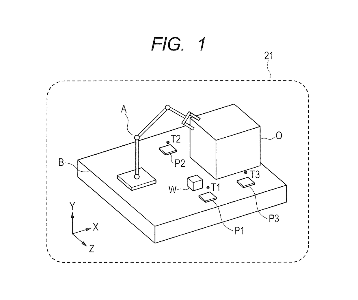
[0117]In the second embodiment, the method for evaluating the layout is changed from that in the first embodiment. That is, in the first embodiment, when the initial layout is generated, only the layout in which the peripheral devices (the work piece rests P1 to P3) and the obstacle O do not interfere with the robot arm A, the inverse kinematics at the teaching point is solved, and the interference avoidance trajectory generation succeeds is left, and the layout which is left is evaluated.

[0118]On the other hand, in the second embodiment, when the initial layout is generated, merely initialization of the position of the particle is performed at random. Namely, it is not checked whether or not the interference occurs, whether or not the inverse kinematics can be solved at the teaching point, and whether or not the interference avoidance trajectory generation succeeds.

[0119]Besides, in the first embodiment, it is conditioned that the robot arm A does not interfere with the peripheral ...

third embodiment

[0167]The third embodiment is different from the first and second embodiments in handling of the layout in which the interference occurs, handling of the layout in which the inverse kinematics calculation of the robot arm A cannot be performed, and handling of the layout in which the interference avoidance trajectory cannot be generated.

[0168]In the first and second embodiments, the optimization calculation is terminated at one time when the layout is evaluated. On the other hand, in the third embodiment, first, the optimization calculation of the layout is performed by using, as the evaluation value concerning the fitness with respect to the specific operation, the number of the teaching points for which the inverse kinematics calculation of the robot arm A can be performed without any interference. In the process of calculation, if even one layout in which the inverse kinematics calculation can be performed at all the teaching points without any interference can be generated, the ...


PUM


Abstract

It becomes possible to optimize setting of a layout of a robot and a peripheral device efficiently and at high speed in a robot workspace. A teaching point acquiring unit acquires a teaching point which corresponds to a specific operation that a robot arm accesses the peripheral device, and through which it allows a reference region of the robot arm to pass. An initial layout generating unit generates an initial layout of the robot arm and the peripheral device. A trajectory generating unit generates a trajectory of the robot arm based on the teaching point. Layout evaluating and layout moving units generate a new layout by changing an arrangement of each device based on the initial layout using a meta-heuristic calculation, set an evaluation value concerning fitness for the specific operation in the initial layout or the new layout, and set the layout based on the set evaluation value.

Description

BACKGROUND OF THE INVENTIONField of the Invention[0001]The present invention relates to a layout setting method and a layout setting apparatus which set a layout for arranging, in a robot workspace including a robot arm and a peripheral device, the robot arm and the peripheral device. Also, the present invention relates to a method of manufacturing parts by the robot arm arranged using the layout setting method and a robot system having the robot arm arranged using the layout setting method.Description of the Related Art[0002]In recent years, in production lines of automobiles and electromechanical (electric) products, working such as welding, assembly and the like is automated by introducing a plurality of industrial robot arms. In such a working environment with robots, robot equipment which comprises at least a robot arm and a peripheral device is arranged. Here, as the peripheral device excluding the robot arm, for example, a work (workpiece), a work piece rest, a jig and the li...

Claims


Application Information

Patent Timeline
IPC IPC(8): B25J9/16
CPCB25J9/1664G05B2219/40515G05B2219/40317B25J9/1671
Inventor KIMURA, GEN
Owner CANON KK
Why Eureka
Try Eureka