Field Deployable Soil Observation Topographic Differential Absorption LiDAR (SOTDiAL)

Inactive Publication Date: 2018-02-08
THE BOARD OF TRUSTEES OF THE UNIV OF ARKANSAS
View PDF6 Cites 3 Cited by
  • Summary
  • Abstract
  • Description
  • Claims
  • Application Information

AI Technical Summary

Benefits of technology

[0009]In other embodiments, the present invention provides a SOTDiAL device will significantly advance the field by allowing for remote measurements of soil condition and soil prop

Problems solved by technology

Current practice requires expensive in situ instrumentation that must be installed and removed by personnel in the field.
Furthermore, data collection is sparse (po

Method used


Image

  • Field Deployable Soil Observation Topographic Differential Absorption LiDAR (SOTDiAL)
  • Field Deployable Soil Observation Topographic Differential Absorption LiDAR (SOTDiAL)
  • Field Deployable Soil Observation Topographic Differential Absorption LiDAR (SOTDiAL)

Examples


Embodiment Construction

[0034]Detailed embodiments of the present invention are disclosed herein; however, it is to be understood that the disclosed embodiments are merely exemplary of the invention, which may be embodied in various forms. Therefore, specific structural and functional details disclosed herein are not to be interpreted as limiting, but merely as a representative basis for teaching one skilled in the art to variously employ the present invention in virtually any appropriately detailed method, structure or system. Further, the terms and phrases used herein are not intended to be limiting, but rather to provide an understandable description of the invention.

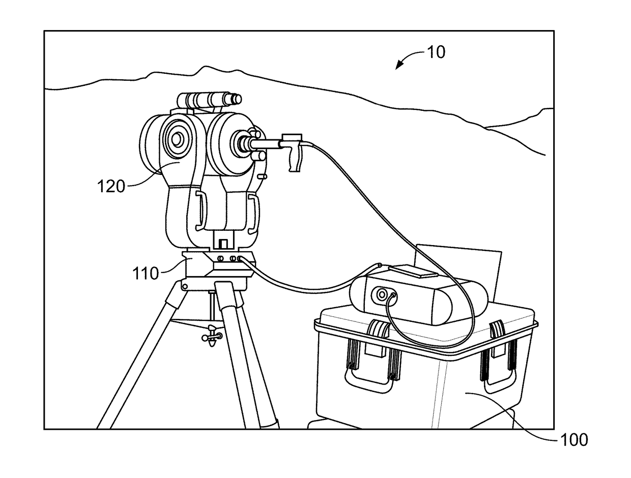
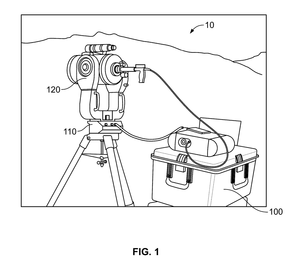
[0035]As shown in FIG. 1, the present invention provides a field deployable SOTDiAL system 10 that is an optical remote sensing instrument. In one preferred embodiment, system 10 includes a 2.5-ft. by 2.5-ft. by 2.5-ft. field box 100 (which contains the heart of the system as well as the data acquisition system), light emitting device 110 a...


PUM


Abstract

A soil analysis system that provides a field deployable device that is configured to remotely measure in situ soil suction through correlation with relative humidity at the soil surface.

Description

RELATED APPLICATIONS[0001]This application claims the benefit of U.S. Provisional Application No. 62 / 371,288 filed Aug. 5, 2016, and herein incorporated by reference.STATEMENT REGARDING FEDERALLY SPONSORED RESEARCH & DEVELOPMENT[0002]This invention was made with government support under No. OASRTRS-14-H-UARK awarded by the United States Department of Transportation Office of the Assistant Secretary for Research and Technology (U.S. DOT / OST-R) under Research and Innovation Technology Administration (RITA) Cooperative Agreement Award. The government has certain rights in the invention.INCORPORATION BY REFERENCE OF MATERIAL SUBMITTED ON A COMPACT DISC[0003]Not applicable.FIELD OF THE INVENTION[0004]Soil suction measurements and soil index properties are important to understanding unsaturated soil mechanics, slope stability, and geo-environmental properties of the soil for its intended use in the field of geotechnical engineering. Current practice requires expensive in situ instrumentat...

Claims


Application Information

Patent Timeline
IPC IPC(8): G01N21/3554G01N21/359G01N33/24G01S17/88
CPCG01N21/3554G01S17/88G01N2201/0612G01N33/246G01N21/359G01N2021/1797
Inventor SALAZAR, SEAN E.COFFMAN, RICHARD A.GARNER, CYRUS D.
Owner THE BOARD OF TRUSTEES OF THE UNIV OF ARKANSAS
Why Eureka
Try Eureka