Cutting head for an intramedullary reamer

Active Publication Date: 2018-02-15
VIANT AS&O HLDG LLC
View PDF0 Cites 9 Cited by
  • Summary
  • Abstract
  • Description
  • Claims
  • Application Information

AI Technical Summary

Benefits of technology

[0013]Furthermore, a protective sleeve may be removably attached to the proximal end of the reamer cutting head. The sleeve provides an alternative means in which to secure the drive shaft to the cutting head. In addition, the sleeve provides a protective covering that minimizes potential disengagement of the shaft from the cutting head. In an embodiment, the sleeve comprises a tapered distal end collar that surrounds the drive shaft and attaches to the cutting head proximal end.
[0014]The cutting head of the present inven

Problems solved by technology

Using a dull reamer generates heat that typically leads to tissue necrosis and results in undesirable patient outcomes.
A non-sterile reamer blade typically results in an infected and damaged intramedullary space that may lead to other problems for the patient.
However, prior art cutting heads have an inefficient blade design which tends to become increasingly dull, particularly when reaming large portions of bone material within a long bone, such as a femur.
Furthermore, because of their high cost, traditional cutter heads are typically reused multiple times. Over time, as these reamer heads are used and reused, the cutting blades become dull.
As a result, these less efficient prior art cutting heads tend to promote an increase

Method used


Image

  • Cutting head for an intramedullary reamer
  • Cutting head for an intramedullary reamer
  • Cutting head for an intramedullary reamer

Examples


Embodiment Construction

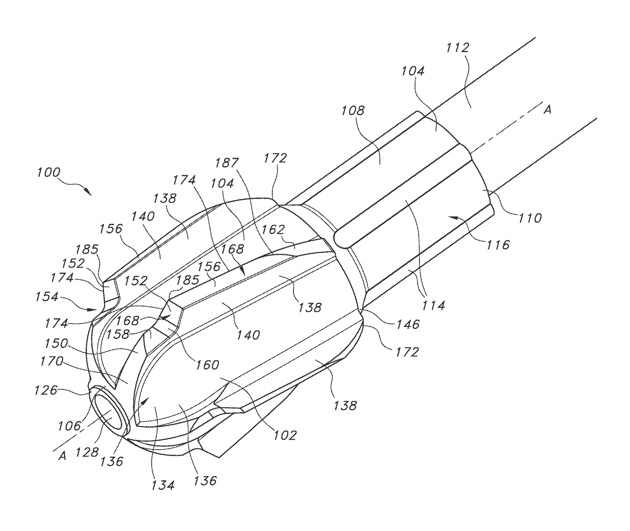
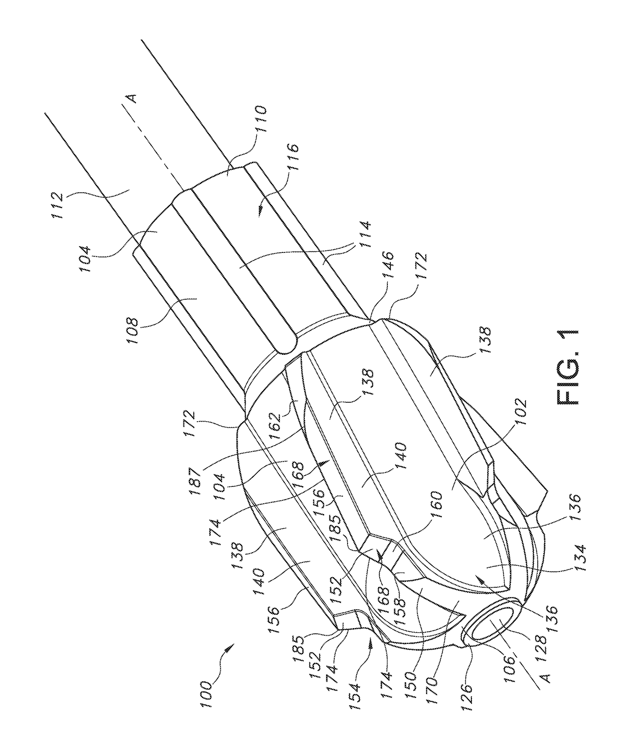
[0028]Now turning to the figures, FIGS. 1-5, 8 and 9 illustrate an embodiment of a cutting head 100 that is configured to cut and remove bone and tissue from the intramedullary canal. As shown in FIG. 1, the cutting head 100 comprises a cylindrically shaped body 102 that extends along longitudinal axis A-A from a distal bone cutting portion 104 having a distal end 106 to a proximal barrel portion 108 having a proximal end 110. The bone cutting portion 104 provides for cutting and removal of bone and tissue from the intramedullary canal during a surgical procedure. The barrel portion 108 provides for a detachable connection of the cutting head 100 to a drive shaft 112 (FIG. 1). For example, a drive shaft 26 connected to a rotary motor (not shown). In an embodiment, a plurality of spaced apart ribs 114 extend outwardly from an exterior barrel surface 116. As shown in FIGS. 1 and 4, the ribs 114 extend axially and are spaced from, but parallel to the longitudinal axis A-A. The pluralit...


PUM


Abstract

A cutting head for use with an intramedullary reamer is described. The reamer cutting head is of a unitary body construction that comprises a conically-shaped body having a bone cutting portion spaced from a barrel portion for attachment to a drive shaft. The bone cutting portion comprises a plurality of blades having a tissue cutting edge that outwardly extends from the cylindrical body. The plurality of blades is positioned about the cutting head in a spaced apart manner. The various plurality of blades are arranged at prescribed angular relationship that increases cutting efficiency and debris removal, thereby reducing reactive torque, axial loading, and head pressure during a surgical procedure.

Description

CROSS-REFERENCE TO RELATED APPLICATION[0001]This application claims priority from U.S. Provisional Patent Application Ser. No. 62 / 374,896, filed Aug. 14, 2016.FIELD OF THE INVENTION[0002]The present invention relates to the art of orthopedic reamers, and more particularly, to cutting heads used for intramedullary reaming.BACKGROUND[0003]Reamers are tools used in orthopedic procedures to cut bone and associated tissue matter. Specifically, the cutting head of the present invention is designed to cut and bore into the intramedullary space or inner canal of a long bone such as a femur, tibia or humerus. Typically, the intramedullary space of a long bone is reamed to clean and create a space for an implant. As such, these reamers are required to be sterile and sharp. Using a dull reamer generates heat that typically leads to tissue necrosis and results in undesirable patient outcomes. A non-sterile reamer blade typically results in an infected and damaged intramedullary space that may l...

Claims


Application Information

Patent Timeline
IPC IPC(8): A61B17/16
CPCA61B17/164A61B17/1617A61B17/1633A61B2017/00982A61B2017/00526A61B2017/0023A61B17/1628A61B2017/00477A61B17/1615
Inventor VICTOR, GARY C.SAUSEN, KARI ANNBRYANT, JACK T.
Owner VIANT AS&O HLDG LLC
Why Eureka
Try Eureka