Surgical tissue marking device with dryer

a tissue marking and dryer technology, applied in the field of biological tissue marking tools, can solve the problems of short-lived drying of wet tissue, achieve the effects of reducing moisture on biological tissue, enhancing the ability to accurately mark desired lines or patterns, and improving surgical outcomes

Active Publication Date: 2018-02-15
TERUMO CARDIOVASCULAR SYST CORP
View PDF5 Cites 3 Cited by
  • Summary
  • Abstract
  • Description
  • Claims
  • Application Information

AI Technical Summary

Benefits of technology

[0008]The present invention provides tools capable of reducing moisture on biological tissue to enhance the ability to accurately mark desired lines or patterns on the tissue using ink or dye. The devices improve surgical outcomes through faster and clearer tissue marking on wet tissue compared to conventional dye marker pens which may tend to produce blurred lines on wet tissue.
[0009]The invention provides a marking device including a “blow-dry feature” to reduce moisture using a flow of drying gas (e.g., pressurized CO2). Drying of the wet tissue may be short lived since surrounding moisture may quickly spread back to the dried area. Therefore, the marker and dryer nozzle are contained within a common housing which allows the user to quickly switch between the drying and marking functions. Preferably, one or both of the marker tip and / or gas nozzle is retractable or otherwise shielded from the other to avoid an airbrush effect wherein the dye may be inadvertently dispersed onto the tissue.

Problems solved by technology

Drying of the wet tissue may be short lived since surrounding moisture may quickly spread back to the dried area.

Method used


Image

  • Surgical tissue marking device with dryer
  • Surgical tissue marking device with dryer
  • Surgical tissue marking device with dryer

Examples


Embodiment Construction

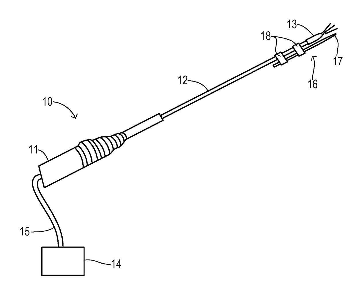
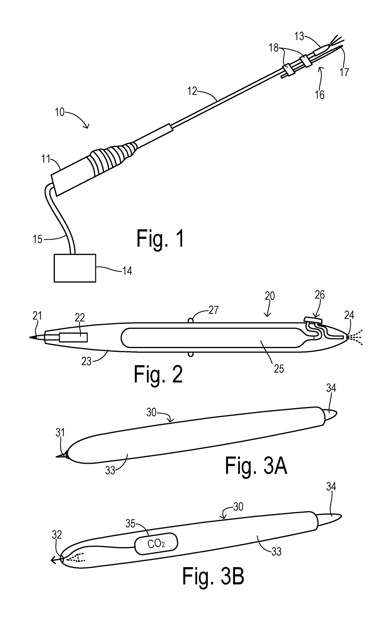
[0017]FIG. 1 shows a combination tool 10 providing blow dryer and marker functions. A handle 11 supports a hollow rod 12 having a nozzle 13 at its distal end. A drying gas such as CO2 is supplied to nozzle 13 through rod 12 and handle 11 from an external source 14 connected by a supply tube 15. The CO2 gas is commonly available in a surgical facility via a standard luer fitting or a gas cartridge or cylinder, for example. A wet tissue area to be marked can be temporarily dried by metering the gas through nozzle 13 toward the area. A marker device 16 with a tip 17 is mounted to rod 12 adjacent nozzle 13 by straps 18. Tip 17 is preferably comprised of a fine tip surgical marker for methylene dye. Alternatively, a laser emitter for ablating tissue to create a mark, a needle or set of needles for creating a tattoo, a heating element for burning a mark, or a cold burn element for burning a mark can be used.

[0018]FIG. 2 shows a self-contained device 20 having an overall cylindrical shape ...


PUM


Abstract

A marking / drying tool applies ink to biological tissue using a single handheld device. A cylindrical body retains a felt tip movable between a retracted position within the body and an extended position outside the body for marking the tissue. A gas source has a manual valve to selectably dispensing a drying gas onto the tissue. In a preferred embodiment, an interlock prevents dispensing of drying gas when the tip is in the extended position and prevents the tip moving to the extended position when the manual valve is dispensing the drying gas.

Description

CROSS REFERENCE TO RELATED APPLICATIONS[0001]This application claims priority to provisional application Ser. No. 62 / 373,563, filed on Aug. 11, 2016, which is incorporated herein by reference in its entirety.STATEMENT REGARDING FEDERALLY SPONSORED RESEARCH[0002]Not Applicable.BACKGROUND OF THE INVENTION[0003]The present invention relates in general to tools for marking biological tissue during surgical procedures, and, more specifically, to improved accuracy and integrity of tissue marking by drying of the biological tissue.[0004]In preparation for cutting, suturing, or other surgical steps, a surgeon may first identify and mark locations on tissue to properly orient and locate targeted tissue. For example, in coronary artery bypass grafting (CABG), a blood vessel is “harvested” (i.e., removed) from its natural location in a patient's body and reattached elsewhere to create a blood flow around a blockage. After a vessel is removed from the patient's body, it must be prepared for use...

Claims


Application Information

Patent Timeline
Patent Type & Authority Applications(United States)
IPC IPC(8): A61B90/00B43K29/00
CPCA61B90/39B43K29/00A61M37/0076A61B18/20A61B2090/3937A61B18/02A61B18/04B43K8/006B43K8/02B43K27/08A61B2090/395A01K11/005A61M37/0084
Inventor KADYKOWSKI, RANDAL JAMES
Owner TERUMO CARDIOVASCULAR SYST CORP
Why Eureka
Try Eureka