Drive mechanism module for a reciprocating pump

a technology of reciprocating pumps and drive mechanisms, applied in the direction of bearings, shafts, liquid cushion bearings, etc., can solve the problems of disassembly, assembly, maintenance, and high cost of the entire pump, and achieve the effect of reducing the cost of production, maintenance and maintenan

Active Publication Date: 2018-02-15
A H M S INC
View PDF10 Cites 19 Cited by
  • Summary
  • Abstract
  • Description
  • Claims
  • Application Information

AI Technical Summary

Problems solved by technology

Such conventional pumps, however, may be expensive and time consuming to produce, repair and maintain due to the number and compl

Method used


Image

  • Drive mechanism module for a reciprocating pump
  • Drive mechanism module for a reciprocating pump
  • Drive mechanism module for a reciprocating pump

Examples


Embodiment Construction

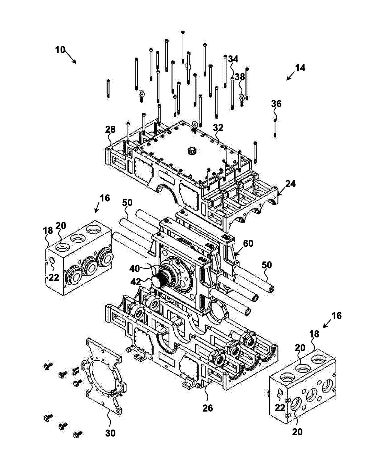
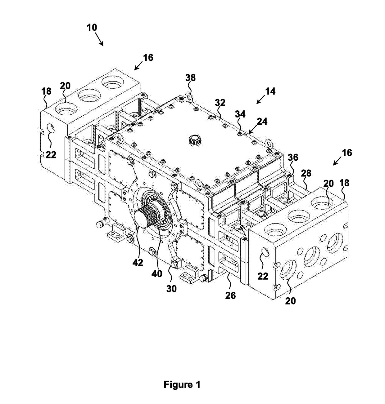
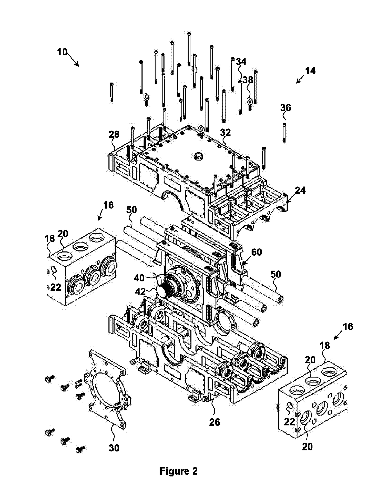
[0046]The present invention relates to a drive mechanism module for use with a reciprocating pump, to a reciprocating pump assembly, and methodologies of converting rotational movement of a drive shaft to reciprocating movement of a reciprocating pump component. Any term or expression not expressly defined herein shall have its commonly accepted definition understood by a person skilled in the art. As used herein, “reciprocating pump” refers to a device for pumping a working fluid, which device has a rotatable drive shaft and at least one reciprocating pump component which may be a plunger, a piston, a diaphragm or a combination of the foregoing. The drive shaft defines a drive shaft axis of rotation and transverse directions that are perpendicular to the drive shaft axis. The reciprocating pump component is reciprocatingly moveable relative to the drive shaft in a first transverse direction while limited in movement relative to the drive shaft in a second transverse direction that ...


PUM


Abstract

A drive mechanism module for use in a reciprocating pump converts rotational movement of a drive shaft to reciprocating movement of a reciprocating pump component transversely to the drive shaft. The drive mechanism module includes a connection member for attachment to the reciprocating pump component, a translating member that drives movement of the connection member in a first transverse direction while reciprocatingly translating in a second transverse direction relative to the connection member, a rotating member that rotates eccentrically with the drive shaft, and a rotary bearing assembly that permits rotation of the rotating member relative to the translating member while driving transverse movement of the translating member. The drive mechanism module may define a bearing fluid path for creating a hydrostatic or hydrodynamic fluid bearing at the interface of the connection member and the translating member.

Description

TECHNICAL FIELD[0001]The present invention relates to a drive mechanism module for converting rotational motion of a drive shaft to reciprocating motion of a reciprocating pump component.BACKGROUND OF THE INVENTION[0002]A conventional reciprocating pump comprises a rotating crankshaft pivotally attached to a connecting rod, which is in turn pivotally connected to a pump component such as a plunger, a piston or a diaphragm, to convert rotational movement of the crankshaft to linear reciprocating movement of the pump component. Such conventional pumps, however, may be expensive and time consuming to produce, repair and maintain due to the number and complexity of mechanical parts, and the potential need to disassemble the entire pump even if damage is isolated to a particular part.[0003]U.S. Patent Application Publication No. 2011 / 0286867 A1 to Lesko discloses a mud pump that includes a frame, a pump module, a pump shaft having an eccentric lobe, a slide movable linearly side-to-side ...

Claims


Application Information

Patent Timeline
IPC IPC(8): F04B9/04F16C32/06
CPCF04B9/045F16C32/064F04B53/16F16C2326/06F04B9/04F04B17/00
Inventor NAGEL, CAREY PHILIPGUEST, FLOYD JAMESPOIRIER, PIERRE-ALEXANDRESALIH, NABEEL
Owner A H M S INC
Why Eureka
Try Eureka