Weapon Fire Detection and Localization Algorithm for Electro-Optical Sensors

a technology of electro-optical sensors and fire detection, applied in the field of image processing, can solve the problems of complex detection methodologies, -optical weapons fire detections often involve severely reduced signature intensities, clutter sources, etc., and achieve the effect of minimizing false detections and high detection rates

Active Publication Date: 2018-02-15
UNITED STATES OF AMERICA THE AS REPRESENTED BY THE SEC OF THE ARMY
View PDF4 Cites 6 Cited by
  • Summary
  • Abstract
  • Description
  • Claims
  • Application Information

AI Technical Summary

Benefits of technology

[0006]A detection method that operates on the output of an imaging detection sensor system based on one or more electro-optical imagers is presented here. The detection method is able to extract weapons fire signatures of high signal intensity in the near field, as well as very low intensity weapons fire signatures in the far field, with a high detection rate. The detection method minimizes false detections from clutter sources. The detection method discriminates weapons fire signatures from background by analyzing charac...

Problems solved by technology

Electro-optical weapons fire detection systems for ground application, capable of detecting short and long range threats require complex detection methodologies to accurately detect weapons fire over a broad dynamic range of signal intensit...

Method used


Image

  • Weapon Fire Detection and Localization Algorithm for Electro-Optical Sensors
  • Weapon Fire Detection and Localization Algorithm for Electro-Optical Sensors
  • Weapon Fire Detection and Localization Algorithm for Electro-Optical Sensors

Examples


Embodiment Construction

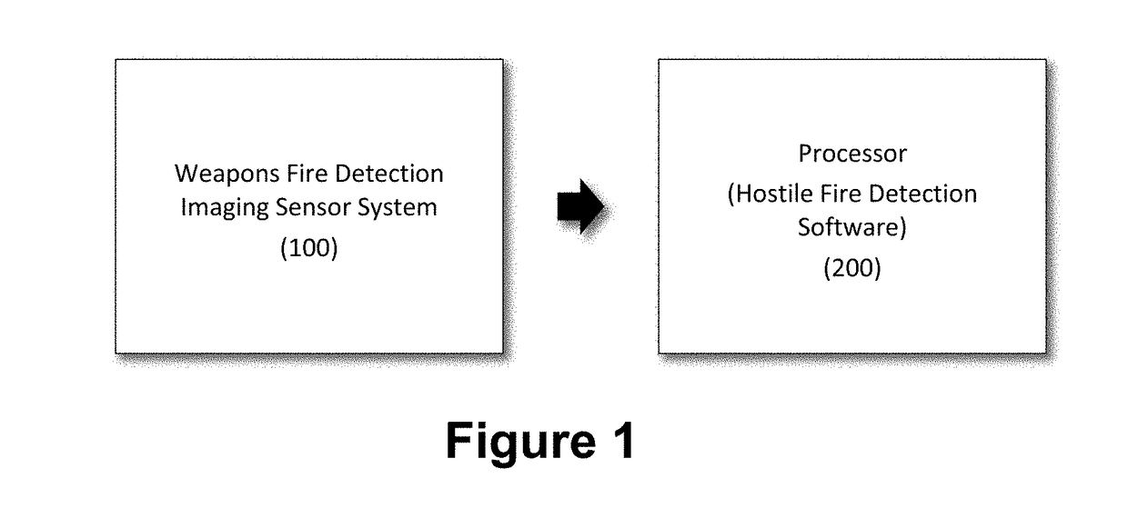
[0017]FIG. 1 shows an exemplary weapon fire detection and localization system based on a weapons fire detection imaging sensor system (100), and a processor (200). Specifically, one embodiment of the weapons fire detection imaging sensor system includes two imaging sensors. The two exemplary imaging sensors, both imaging in separate infrared bands, operate at a frame rate of greater than 60 Hz and have a focal plane array (FPA) size of at least 640 by 480. The video outputs of the associated detection sensors are provided as inputs to the processor. The processor hosts the weapons fire detection and localization algorithm.

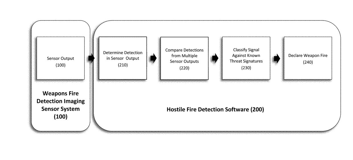
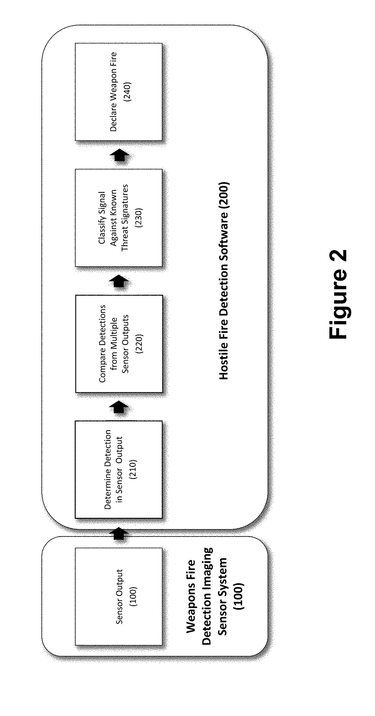
[0018]FIG. 2 describes an exemplary weapons fire detection and localization algorithm. For each imaging detection sensor (100), the video output is provided to the processor. Weapon fire detections are determined from the independent video output of each imaging detection sensor in the weapon fire detection sensor system (210). As an example, one embodiment of the ...


PUM


Abstract

A method is disclosed for detecting and locating a blast, including muzzle flash, created by the launch of a projectile from a gun barrel, rocket tube or similar device, generally associated with weapons fire. The method is used in conjunction with electro-optical imaging sensors and provides the azimuth and elevation from the detecting sensor to the launch location of the blast and also provides the weapon classification.

Description

GOVERNMENT INTEREST[0001]The invention described herein may be manufactured, used, sold, imported, and / or licensed by or for the Government of the United States of America.FIELD OF THE INVENTION[0002]The present invention relates to the field of image processing, and in particular, a method for detecting and locating a blast, including muzzle flash, created by the launch of a projectile from a gun barrel, rocket tube or similar device, generally associated with weapons fire.STATEMENT REGARDING PRIOR DISCLOSURES BY THE CO-INVENTORS[0003]A presentation co-authored by Jeremy Brown, Jami Davis, and Josh Gabonia (the co-inventors), entitled, “Clutter Mitigation for Ground Vehicle Hostile Fire Detection and Location (HFDL) Using EOIR Sensors,” was submitted to the Military Sensing Symposia for a closed MSS Passive Sensors Parallel Symposium (Proceeding of MSS 2015), held September 2015.BACKGROUND OF THE INVENTION[0004]Weapon fire detection and localization can be accomplished using a vari...

Claims


Application Information

Patent Timeline
IPC IPC(8): G06T7/00H04N5/225H04N5/33F41H13/00G01S11/12G06V20/00
CPCG06T7/001F41H13/00H04N5/2258H04N5/33G01S11/12G01S3/78G06T2207/10016G06T2207/10048G06T2207/30212G06T7/73G06V20/00H04N23/45G06F18/00
Inventor BROWN, JEREMY B.HUTCHISON, III, JOHN E.DAVIS, JAMI H.GABONIA, JOSHUA K.
Owner UNITED STATES OF AMERICA THE AS REPRESENTED BY THE SEC OF THE ARMY
Why Eureka
Try Eureka