
Piezoelectric energy harvesting system from vehicle's tires

a technology of energy harvesting system and vehicle tires, which is applied in the direction of generator/motor, vehicle sub-unit features, transportation and packaging, etc., can solve the problems of negative affecting system efficiency and energy loss, and achieve the effect of efficiently converting energy, not easily damaged or deformed, and efficient transmission of electrical energy

Inactive Publication Date: 2018-02-22
GHANBARI MASOUD +1
View PDF219 Cites 12 Cited by
  • Summary
  • Abstract
  • Description
  • Claims
  • Application Information

AI Technical Summary

Benefits of technology

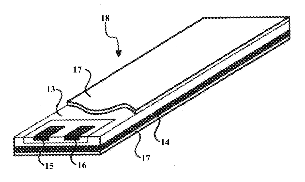
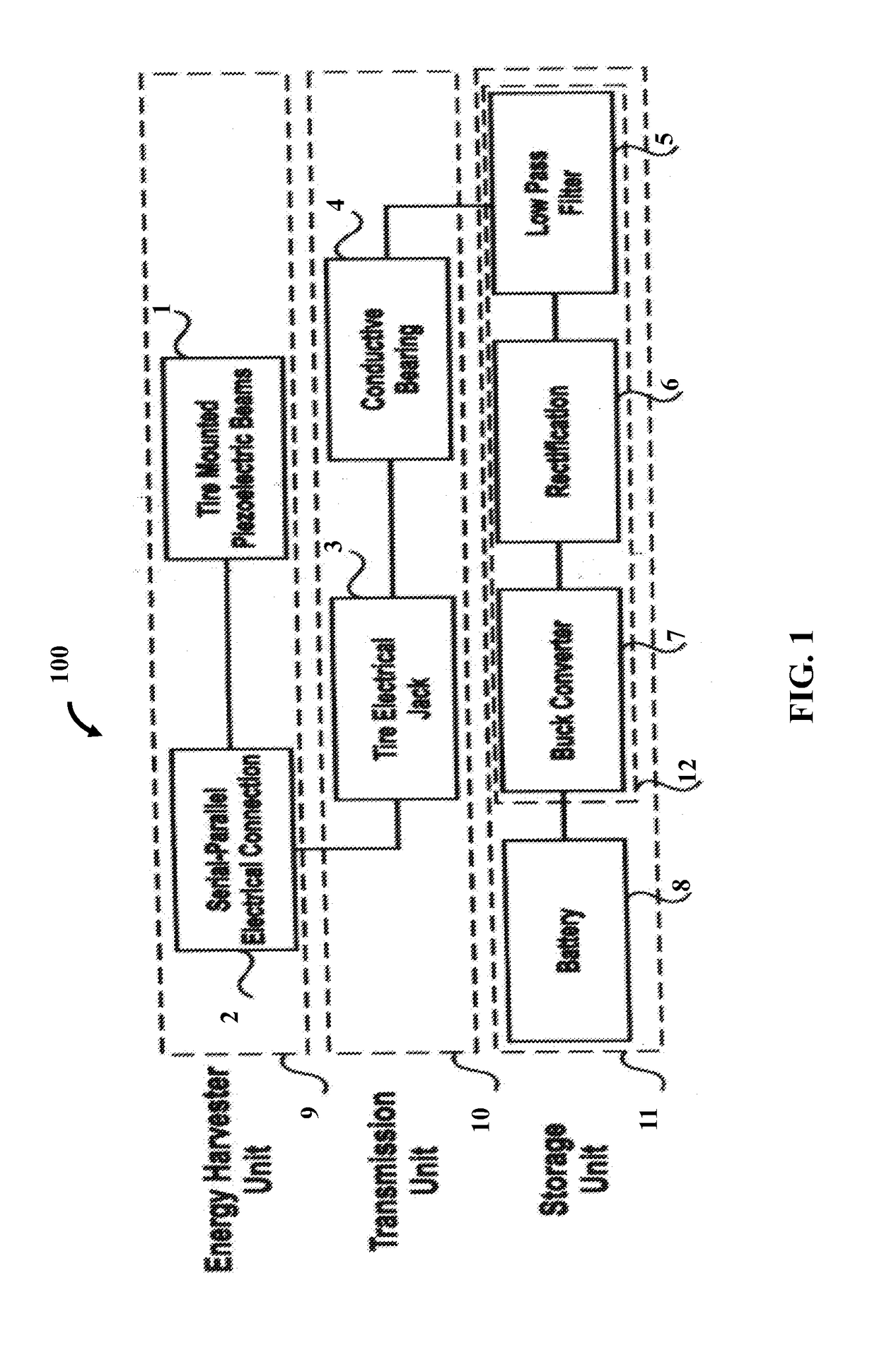
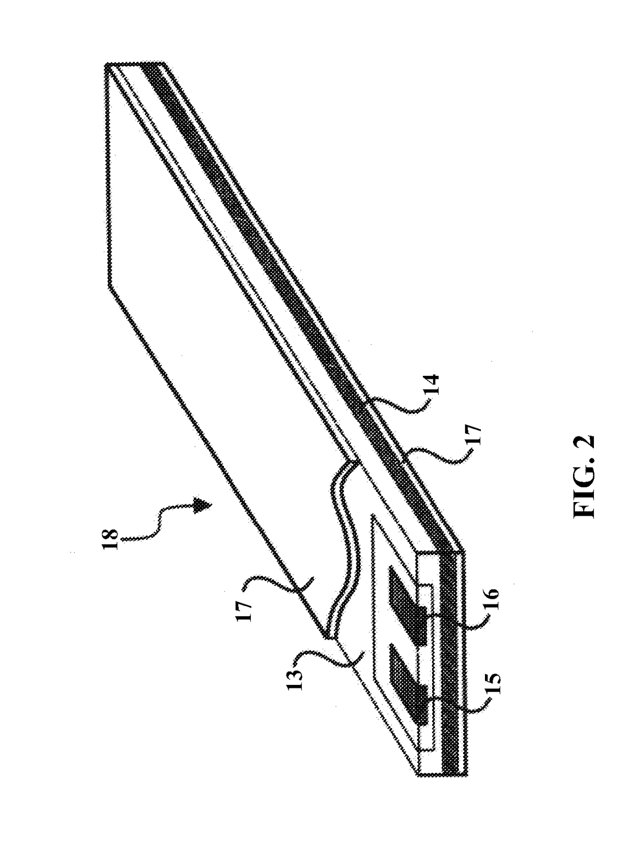
The patent proposes a system for harvesting energy from moving vehicle tires and supplying it to electrical devices in the car. The method involves mounting piezoelectric stacks between the tire layers, and a wire-based energy transmission system to protect and save the scavenged power. The system needs to be protected from physical tensions and temperature affects, so an appropriate insulation is required. The patent also addresses energy loss in the tire electrical jack and conductive bearing, and proposes measures to prevent it. Overall, the patent aims to provide a more efficient and reliable system for harvesting and supplying energy in vehicles.

Problems solved by technology

Furthermore, the temperature will negatively affect the system's efficiency as it has an inverse relation with conductivity.
Energy loss is not merely in the conductive wire and it can occur in the tire electrical jack and the conductive bearing.

Method used


Image

  • Piezoelectric energy harvesting system from vehicle's tires
  • Piezoelectric energy harvesting system from vehicle's tires
  • Piezoelectric energy harvesting system from vehicle's tires

Examples


Embodiment Construction

[0035]A description of embodiments of the present invention will now be given with reference to the Figures. It is expected that the present invention may be embodied in other specific forms without departing from its spirit or essential characteristics. The described embodiments are to be considered in all respects only as illustrative and not restrictive. The scope of the invention is, therefore, indicated by the appended claims rather than by the foregoing description. All changes that come within the meaning and range of equivalency of the claims are to be embraced within their scope.

[0036]In the context of harvesting energy from a vehicle tire, conventionally, piezoelectric beams were placed on the inner surface of a vehicle's tire for energy harvesting. In the case of inner surface attachment, the strain applied to the piezoelectric material is low. This structure had low efficiency and was not feasible for industrial application. Alternately, piezoelectric beams were position...


PUM


Abstract

A piezoelectric energy harvesting system for converting mechanical energy of a tire of a vehicle to electrical energy includes sets of piezoelectric beam assemblies, a tire electrical jack, a conductive bearing, and an electrical storage unit. The sets of piezoelectric beam assemblies are embedded in multiple layers of the tire of the vehicle and electrically connected in a parallel configuration. Each of the sets of the piezoelectric beam assemblies are electrically connected in a series configuration for converting mechanical strains into electrical energy. The tire electrical jack is mounted on a rim of the tire and receives the electrical energy generated by the sets of piezoelectric beam assemblies via output terminals. The conductive bearing transmits the electrical energy received by the tire electrical jack to the electrical storage unit, which filters, rectifies, adapts and stores the transmitted electrical energy for powering components of the vehicle.

Description

BACKGROUND OF THE INVENTION[0001]Limited resources of energy despite the exponentially increasing amount of its demand have forced researchers to explore and use renewable resources of energies, for example, wind energy, solar energy, etc. Among those that convert nature inspired energy to electrical energy, piezoelectric beams, which turn ambient mechanical vibrations into electrical power, are also of great interest. There exist several commercially available devices that are able to convert mechanical pressure into an electric signal, for example, Seiko Kinetic watch, mechanical wind up radios, piezoelectric igniter, etc.[0002]The word ‘piezo’ is derived from the Greek word for pressure. The piezoelectric effect was discovered in 1880 in an attempt to find out how pressure will turn into electricity. It was noticed when pressure is applied to a quartz crystal, this component acts as an energy transfer function between mechanical and electrical energies. However, later it was foun...

Claims


Application Information

Patent Timeline
Patent Type & Authority Applications(United States)
IPC IPC(8): H01L41/113H02J7/02B60L11/00B60L1/00B60L11/18B60C19/00
CPCH01L41/1134H02J7/025B60L11/002B60L2210/00B60L11/1879B60C19/00B60L1/00B60B21/00H02J7/32B60Y2400/209Y02T10/7072Y02T90/14B60L53/00B60K25/08H02N2/186H02N2/181B60L53/50H02J50/001Y02T10/70Y02T90/12H10N30/304H02N2/188Y02T10/90
Inventor GHANBARI, MASOUDAMJADY, NIMA
Owner GHANBARI MASOUD
Learn More