Protecting an optical particle sensor from particulate desposits by thermophoresis

a technology of thermophoresis and optical particle sensor, which is applied in the direction of auxillary pretreatment, instruments, separation processes, etc., can solve the problems of affecting the detection accuracy of optical particle sensors

Active Publication Date: 2018-03-01
KONINKLJIJKE PHILIPS NV
View PDF0 Cites 6 Cited by
  • Summary
  • Abstract
  • Description
  • Claims
  • Application Information

AI Technical Summary

Benefits of technology

[0017]This arrangement uses thermophoretic induced movement of entrained matter, in particular particles, to steer matter away from a particle sensor component. In this way it can be controlled which particles are sensed by the particle sensor component.
[0018]The heating arrangement may comprise a Peltier heater. This provides an efficient and low cost implementation. The heating arrangement may comprise a thermal coupling between an existing heat-generating component of the system which is provided to perform a non-heating function. For example, a light source generates heat in addition to its main function of generating light. This heat can be coupled to the component to be protected to drive particulate matter away. Alternatively, an active heat source may be provided on or adjacent the component. This may for example be a Joule heating wire grid.
[0019]The device may further comprise a cooling arrangement which combines with the heating arrangement to induce the thermophoretic particle movement. This enables more active thermophoretic behavior. The cooling arrangement may also comprise a Peltier device, functioning as a cooler.
[0026]If the input flow channel is large, the thermophoretic effect may be reduced. The input flow channel may then be divided into input sub-channels, each sub-channel having a respective heating arrangement thereby to generate respective first (warmer) and second (cooler) regions of the input sub-channel. The sub-channel first regions may then together couple to the first output flow region and the sub-channel second regions may then together couple to the second output flow region.
[0027]This enables the entrained matter to be moved more effectively between the output flow regions.
[0031]According to another particular embodiment of the invention, the sensor and the thermophoretic arrangement are moveable relative to each other. The means for changing a length of the space allows increasing or decreasing the space by moving the thermophoretic arrangement and the sensor relative to each other. For example, a mechanical structure may be provided which features the sensor and the thermophoretic arrangement and which allows the distance between the two elements to be changed.

Problems solved by technology

Especially in China, excessive PM2.5 pollution has become a common problem in the last decade.
For many sensors, the operation principles result in a response to other compounds than the target compound, leading to incorrect readings when a target compound and an interfering compound are present simultaneously.
A known solution is to put a physical filter in front of the sensor to block suspended solids and liquids, however, over time this filter will get blocked and reduce the air flow through the sensor.

Method used


Image

  • Protecting an optical particle sensor from particulate desposits by thermophoresis
  • Protecting an optical particle sensor from particulate desposits by thermophoresis
  • Protecting an optical particle sensor from particulate desposits by thermophoresis

Examples


Embodiment Construction

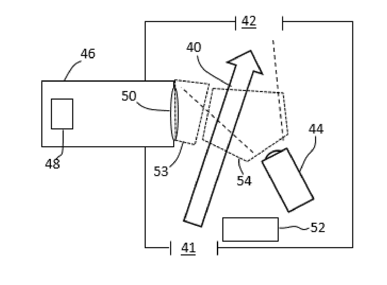
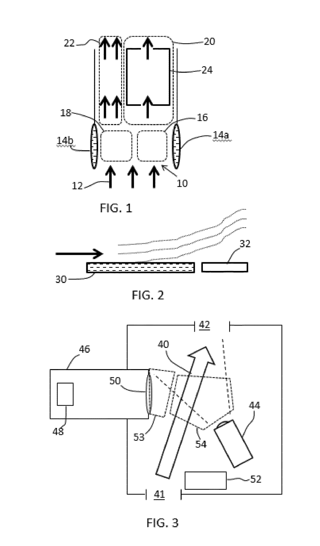
[0049]The invention provides a system comprising a particle sensing component, and a heating arrangement to induce thermophoretic particle movement away from the component. This mechanism may be used in a sensor device which comprises an input flow channel for receiving a gas flow with entrained matter to be sensed. The heating arrangement is used to induce thermophoretic particle movement from a first, warmer, region of the input flow channel to a second, cooler, region of the input flow channel. A sensor comprises the particle sensor component) at or downstream of the first region of the input flow channel. This way, filtering can be performed without the need for a physical filter.

[0050]In this sensor device, thermophoresis is used to move particles from the air path of sensors or key components of such sensors. In doing so, the sensor or specific components thereof can be protected without the need for a physical filter to block particles.

[0051]The force which is induced during ...


PUM

PropertyMeasurementUnit
diameteraaaaaaaaaa
concentrationsaaaaaaaaaa

Abstract

The invention provides a sensor device which comprises an input flow channel (10) for receiving a gas flow with entrained matter to be sensed. A thermophoretic arrangement (14a, 14b) is used to induce a thermophoretic particle movement from a first, warmer, region (16) of the input flow channel to a second, cooler, region (18) of the input flow channel (10). A sensor (24) comprises a particle sensor component at or downstream of the first region (16) of the input flow channel (10). The invention provides the benefit of pre-filtering (e.g. removal of most suspended solids / liquids) without the need for a physical filter that can become blocked.

Description

FIELD OF THE INVENTION[0001]This invention relates to a sensor device and method for detecting targets within a gas flow, such as particulate matter.BACKGROUND OF THE INVENTION[0002]DE102008041809 discloses a method for operating a particle sensor. In a phase in which no measurements take place, a heater is set to a temperature to avoid particle deposition at electrodes used for particle measurement. Avoiding particle deposition can, for example, be based on thermophoresis.[0003]Airborne particle pollution, especially particle matter size less than 2.5 μm diameter range (named “PM2.5”), is a big concern for countries like China, where the speed of industrialization stretches the boundaries of regulatory requirements.[0004]As a consequence of increasing consumer empowerment, the demand for information about the air quality of living spaces is increasing. Especially in China, excessive PM2.5 pollution has become a common problem in the last decade. This problem is also validated by co...

Claims


Application Information

Patent Timeline
Patent Type & Authority Applications(United States)
IPC IPC(8): B01D49/02G01N21/15G01N21/53
CPCB01D49/02G01N21/15G01N21/53G01N2021/155G01N2015/0046G01N2015/0019G01N15/06G01N2015/0693G01N15/02B01D51/02G01N1/2247
Inventor KELLY, DECLAN PATRICKSCHEJA, MICHAEL MARTINRONDA, CORNELIS REINDERKARAKAYA, KORAYSUIJVER, JAN FREDERIK
Owner KONINKLJIJKE PHILIPS NV
Why Eureka
Try Eureka