Method and system for laser machining of relatively large workpieces

Pending Publication Date: 2018-03-01
ACS MOTION CONTROL +1
View PDF10 Cites 20 Cited by
  • Summary
  • Abstract
  • Description
  • Claims
  • Application Information

AI Technical Summary

Benefits of technology

[0025]The embodiments may enhance the capabilities of existing laser scanners, which are characterized by a limited field of view (FOV) and therefore a limited work area, by enslaving a separate existing stage controller to the scanner, thus overcoming the limited FOV and work area limitation.
[0026]It is noted that developing a single system that can manage both subsystems makes sense, but would require a huge development effort estimated at some 20 to 50 man-years to cover all sizes of stages and power needs. Providing a method to make the two existing systems work together and give the level of performance needed may save a huge amount of effor

Problems solved by technology

Each scanner can move the laser beam at a very high speed and acceleration but over a limited area due to the limited Field Of View (FOV) of the scanner, which is typically below 100 mm×100 mm.
The speed of moving the workpiece is relatively low when compared to moving a laser beam with a scanner and results in low throughput processing.
The throughput is negatively affected, relatively to a system with scanner only, by the repeated move and settle times of the XY stage during which the Laser is deactivated, and the accuracy is limited by stitching errors.
Stitching errors result from the misalignment of adjacent FOV tiles, which is mainly because of the lens nonlinearity which is especially present at the border of the FOV, as any overall scanner and servo inaccuracies can manifest at the border or seam of adjacent blocks.
When one controller manages both the stage and the scanner it requires high processing power and correspondingly expensive controll

Method used


Image

  • Method and system for laser machining of relatively large workpieces
  • Method and system for laser machining of relatively large workpieces
  • Method and system for laser machining of relatively large workpieces

Examples


Example

[0073]The present invention, in some embodiments thereof, relates to laser machining using laser scanners and an XY stage and also to a bridge to synchronize and transfer data between two real time control systems.

[0074]Before explaining at least one embodiment of the invention in detail, it is to be understood that the invention is not necessarily limited in its application to the details of construction and the arrangement of the components and / or methods set forth in the following description and / or illustrated in the drawings and / or the Examples. The invention is capable of other embodiments or of being practiced or carried out in various ways.

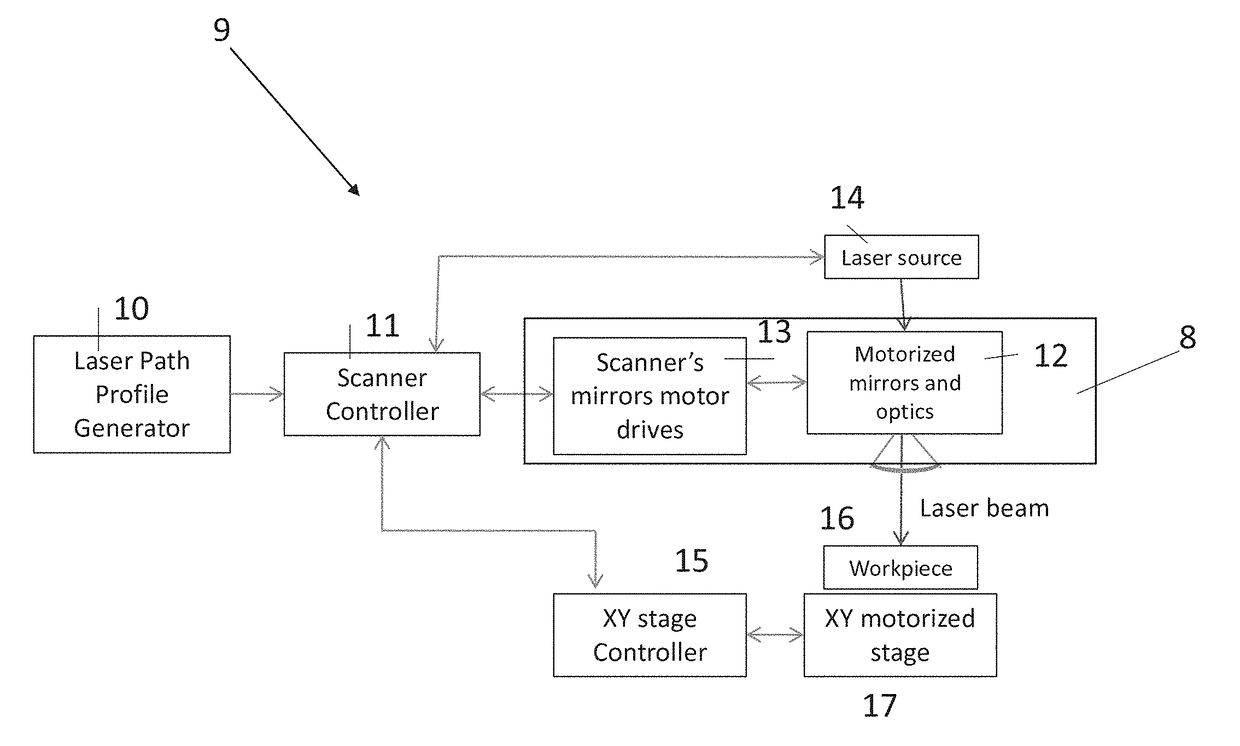
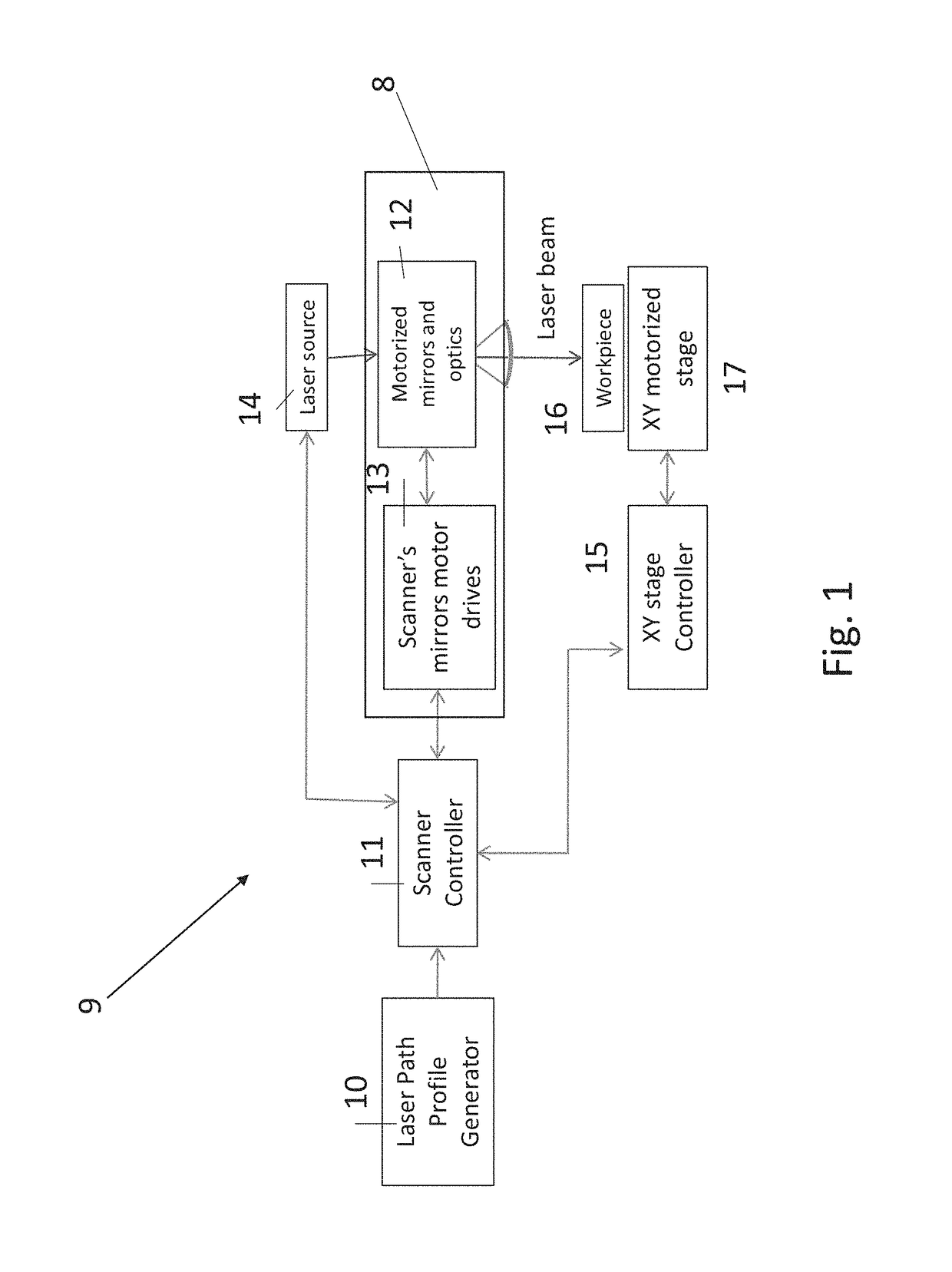
[0075]Referring now to the drawings, FIG. 1 is a simplified schematic block diagram showing a laser system 9 for workpieces which is made up of an XY stage that holds the workpiece and a laser scanner. The XY stage carries the workpiece and has its own drive motor and its own controller. Alternatively, the workpiece may be stationary and t...


PUM

PropertyMeasurementUnit
Mechanical propertiesaaaaaaaaaa
Frequencyaaaaaaaaaa
Optical propertiesaaaaaaaaaa

Abstract

A laser machining device comprises a movable stage which is controlled by a stage controller. A laser produces a beam for machining and the beam is scanned over the part using a laser scanner under control of the laser scanner. The scanner controller controls the stage controller to synchronize movements of the stage with movements of the scanner. The stage may carry the part to be machined or the scanner.

Description

RELATED APPLICATIONS[0001]This application claims the benefit of priority under 35 USC §119(e) of U.S. Provisional Patent Application Nos. 62 / 476,907, filed on Mar. 27, 2017, and 62 / 380,443, filed on Aug. 28, 2016. The contents of the above applications are all incorporated by reference as if fully set forth herein in their entirety.FIELD AND BACKGROUND OF THE INVENTION[0002]The present invention, in some embodiments thereof, relates to laser machining using laser scanners and an XY stage and also to a bridge to synchronize and transfer data between two real time control systems.[0003]A system and method of moving a laser beam along a desired path relative to a workpiece and delivering pulses of laser beam at uniformly spaced intervals and / or at pre-assigned locations along the desired path on the workpiece, where the system is comprised of two sub-systems, a cluster of one or more laser scanners that each steers a laser beam and fires the laser pulses and a motorized mechanical XY ...

Claims


Application Information

Patent Timeline
IPC IPC(8): B23K26/082B23K26/08G05B19/19
CPCB23K26/082B23K26/0853G05B2219/42219G05B2219/45041G05B19/19B23K26/0604B23K26/21G05B19/402
Inventor KRAMER, BOAZKIRSHENBOIM, ZE'EVDOTLINGER, ALEXANDER MARKUS
Owner ACS MOTION CONTROL
Why Eureka
Try Eureka