AI technical title is built by PatSnap AI team. It summarizes the technical point description of the patent document.
a detection method and automatic technology, applied in the direction of navigation instruments, using reradiation, instruments, etc., can solve the problems of large storage space and bandwidth, illustration is merely representational, and may not be drawn to scal
Active Publication Date: 2018-03-01
HERE GLOBAL BV
View PDF0 Cites 37 Cited by
Summary
Abstract
Description
Claims
Application Information
AI Technical Summary
This helps you quickly interpret patents by identifying the three key elements:
Problems solved by technology
Method used
Benefits of technology
Benefits of technology
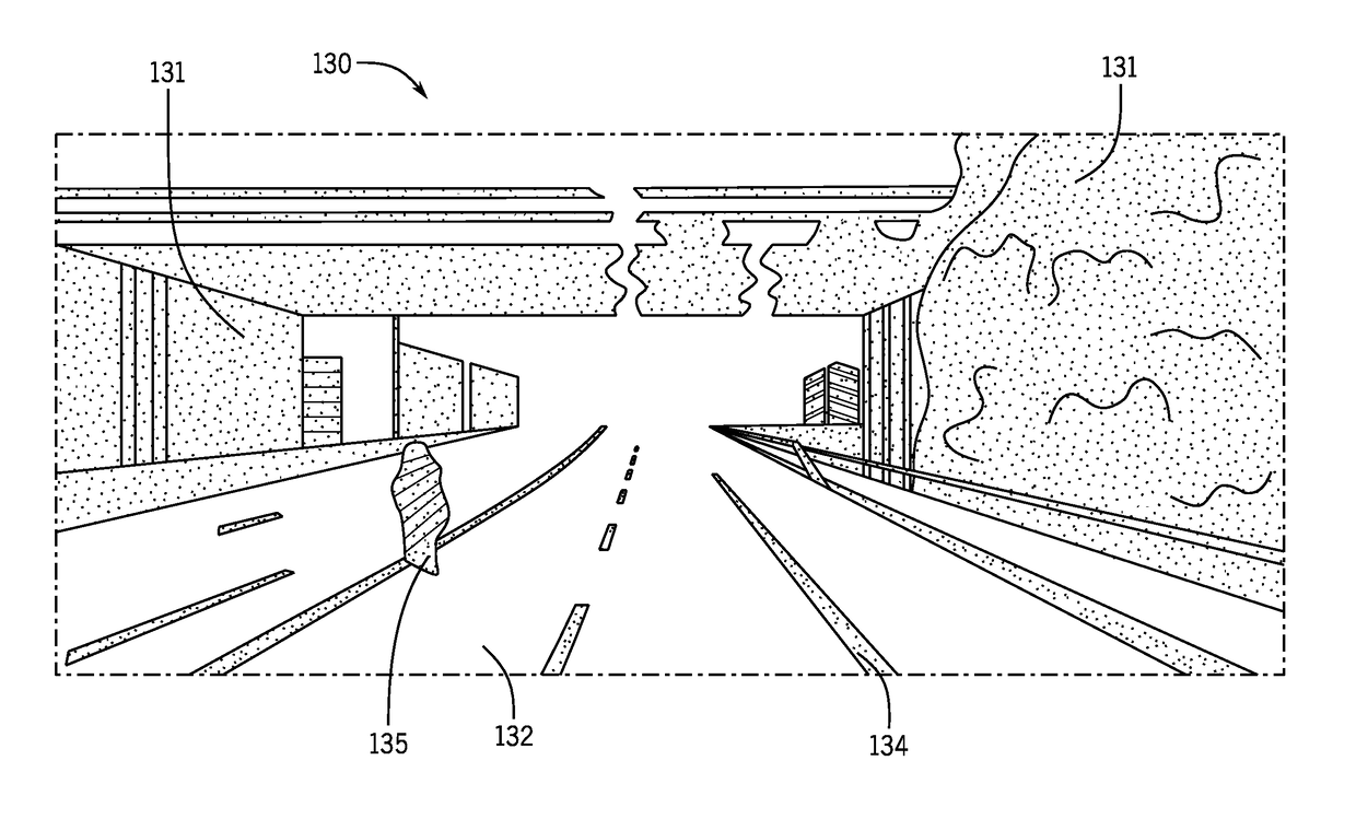
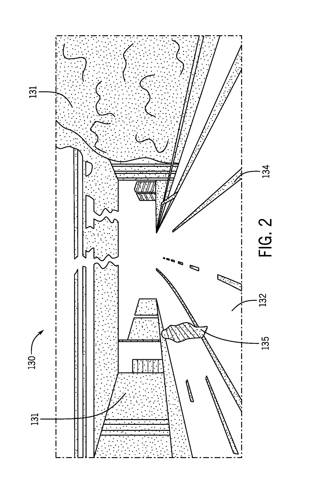
The patent describes a method, apparatus, and system for automatically creating a map of a roadway using point cloud data collected by a distance sensor. The point cloud data is reduced to a smaller volume around the roadway and projected onto a two-dimensional map. The system uses a voxel occupancy value to define the shape of the roadway. This invention helps to improve the precision and accuracy of mapping roadways for autonomous vehicles.
Problems solved by technology
Localization techniques that match a location to a map or environment face additional challenging in improving this accuracy.
Voxels for a three-dimensional space require a vast amount of storage space and bandwidth in order to be communicated in a mobile system.
In some examples, the volumetric grid, even when reduced through the analysis in the two-dimensional plane, may include large amounts of empty space.
Additionally, the illustrations are merely representational and may not be drawn to scale.
Method used
Image
Click on the blue label to locate the original text in one second.
Reading with bidirectional positioning of images and text.
Examples
embodiment 1
[0140]A method for automatic generation of a localization geometry, the method comprising:
[0141]receiving point cloud data collected by a distance sensor and describing a vicinity of a pathway;
[0142]reducing, by a processor, the point cloud data to a predetermined volume with respect to the pathway;
[0143]projecting, by the processor, the point cloud data to a two-dimensional plane including at least one pixel formation;
[0144]defining, by the processor, a volumetric grid according to the at least one pixel formation;
[0145]determining, by the processor, a voxel occupancy for each of a plurality of voxels forming the volumetric grid; and generating, by the processor, the localization geometry according to the voxel occupancy.
embodiment 2
[0146]The method of embodiment 1, wherein reducing the point cloud data to the predetermined volume includes:
[0147]determining a first horizontal border of the pathway;
[0148]determining a second horizontal border of the pathway; and
[0149]filtering data of the point cloud data to remove data between the first horizontal border and the second horizontal border.
embodiment 3
[0150]The method of embodiments 1-2, wherein reducing the point cloud data to the predetermined volume includes:
[0151]determining a first vertical border in a plane parallel to the pathway;
[0152]determining a second vertical border in a plane parallel to the pathway; and
[0153]filtering data of the point cloud data to remove data between the first vertical border and the second vertical border.
PUM
Abstract
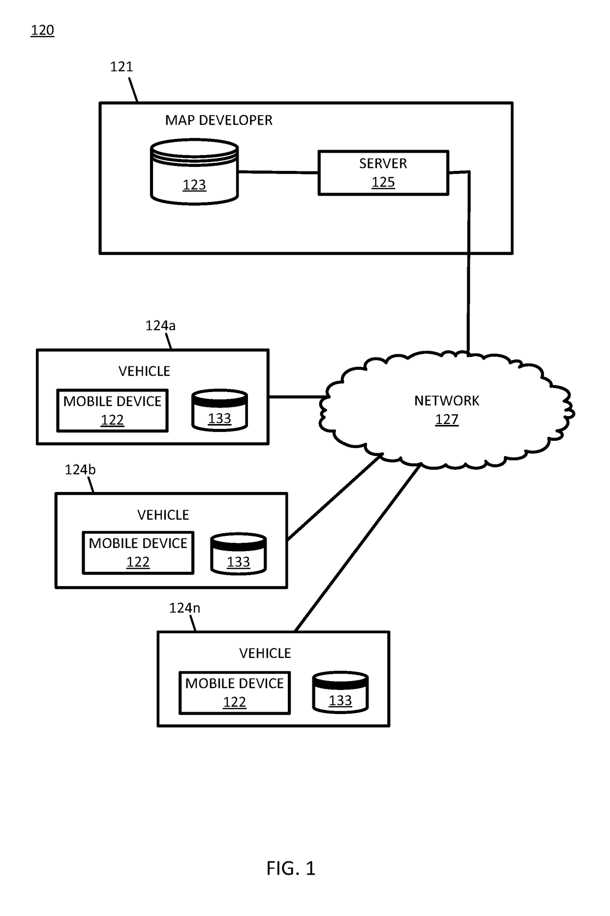
Embodiments include apparatus and methods for generating a localization geometry or occupancy grid for a geographic location. Point cloud that describes a vicinity of a pathway is collected by a distance sensor and describing a vicinity of the pathway. The point cloud data is reduced or filtered to a predetermined volume with respect to the roadway. The remaining point cloud data is projected onto a two-dimensional plane including at least one pixel formation. A volumetric grid is defined according to the at least one pixel formation, and a voxel occupancy for each of a voxels forming the volumetric grid is determined. The arrangement of the voxel occupancies or a sequence of data describing the voxel occupancies is a localization geometry that describes the geographic location of the pathway.
Description
FIELD[0001]The following disclosure relates to detection of a vicinity of a roadway and generation of an occupancy grid for a signature of the vicinity of the roadway, and in addition, applications for the signature of the vicinity of the roadway.BACKGROUND[0002]The Global Positioning System (GPS) or another global navigation satellitesystem (GNSS) provides location information to a receiving device anywhere on Earth as long as the device has a substantial line of sight without significant obstruction to three or four satellites of the system. The GPS system is maintained and made available by the United States government. Originally, the government retained exclusive use of GPS. Over time increasing levels of accuracy of the GPS signals were made available to the public.[0003]Accuracy of the GPS system alone is about 50 feet or 15 meters. The accuracy may be augmented using secondary techniques or systems such as the Wide AreaAugmentation System (WAAS), Differential GPS (DGPS), i...
Claims
Application Information
Patent Timeline
Application Date:The date an application was filed.
Publication Date:The date a patent or application was officially published.
First Publication Date:The earliest publication date of a patent with the same application number.
Issue Date:Publication date of the patent grant document.
PCT Entry Date:The Entry date of PCT National Phase.
Estimated Expiry Date:The statutory expiry date of a patent right according to the Patent Law, and it is the longest term of protection that the patent right can achieve without the termination of the patent right due to other reasons(Term extension factor has been taken into account ).
Invalid Date:Actual expiry date is based on effective date or publication date of legal transaction data of invalid patent.

