Magnetic field distortion calculation device, method, and program

Inactive Publication Date: 2018-03-01
FUJIFILM CORP
View PDF5 Cites 0 Cited by
  • Summary
  • Abstract
  • Description
  • Claims
  • Application Information

AI Technical Summary

Benefits of technology

[0020]Therefore, based on the first and second deformation vectors, it is possible to calculate the deformation due to the relative magnetic field distortion between the first and second th

Problems solved by technology

However, in the MRI image acquired by the MRI apparatus, geometric distortion due to an apparatus and geometric distortion (referred to as magnetic field distortion) due to a subject occur due to non-uniformity in a static magnetic field and incompleteness in a gradient magnetic field.
However, if the magnetic field distortion is included in two MRI images with different imaging timings for follow-up on the same subject, it is not possible to accurately determine the progress.
However, if magnetic field distortion is included in the MRI image, it is not possible to distinguish whether the recognized atrophy of the brain is caused by the progress of the disease or by the magnetic field distortion.
On the other hand, in the MRI apparatus, magnetic f

Method used


Image

  • Magnetic field distortion calculation device, method, and program
  • Magnetic field distortion calculation device, method, and program
  • Magnetic field distortion calculation device, method, and program

Examples


Example

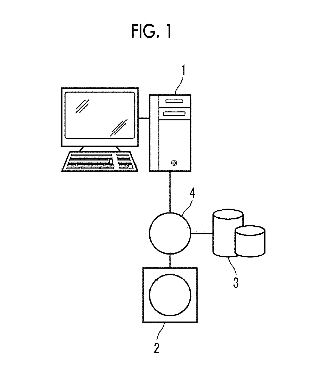
[0036]Hereinafter, embodiments of the present invention will be described with reference to the diagrams. FIG. 1 is a hardware configuration diagram showing an overview of a diagnosis assistance system to which a magnetic field distortion calculation device according to a first embodiment of the present invention is applied. As shown in FIG. 1, in the diagnosis assistance system, a magnetic field distortion calculation device 1 according to the present embodiment, a three-dimensional imaging apparatus 2, and an image storage server 3 are communicably connected to each other through a network 4. Then, in the diagnosis assistance system, the magnetic field distortion calculation device 1 compares two three-dimensional images with different imaging timings for comparative diagnosis of a diagnosis target part of the subject.

[0037]The three-dimensional imaging apparatus 2 is an apparatus that generates a three-dimensional image showing a part, which is a diagnosis target part of the subj...


PUM


Abstract

A region extraction unit extracts first and second shape-invariant regions corresponding to each other from first and second three-dimensional images acquired by an MRI apparatus. A first registration unit acquires a first deformation vector by performing rigid registration between the first and second shape-invariant regions. A second registration unit acquires a second deformation vector by performing non-rigid registration between the first and second three-dimensional images in each shape-invariant region. A magnetic field distortion vector calculation unit calculates a magnetic field distortion vector, which represents relative magnetic field distortion between the first and second three-dimensional images based on the first and second deformation vectors.

Description

CROSS REFERENCE TO RELATED APPLICATIONS[0001]The present application claims priority under 35 U.S.C. §119 to Japanese Patent Application No. 2016-162464 filed on Aug. 23, 2016. The above application is hereby expressly incorporated by reference, in its entirety, into the present application.BACKGROUNDField of the Invention[0002]The present invention relates to a magnetic field distortion calculation device, method, and program for calculating magnetic field distortion included in a three-dimensional image acquired by a magnetic resonance imaging (MRI) apparatus.Description of the Related Art[0003]In recent years, due to advances in medical apparatuses such as computed tomography (CT) apparatuses and MRI apparatuses, high-quality three-dimensional images with high resolution are used for image diagnosis. Here, the CT apparatus can image the inside of the body of a subject in a short time. Accordingly, the CT apparatus is used for early detection of a disease and surgical planning in ...

Claims


Application Information

Patent Timeline
IPC IPC(8): G06T5/00G06T7/38
CPCG06T5/006G06T7/38G06T2207/30016G06T2207/20G06T2207/10088G06T7/97G06T7/30
Inventor MASUMOTO, JUN
Owner FUJIFILM CORP
Why Eureka
Try Eureka