
Orientation degree distribution calculation method, orientation degree distribution analyzer, and orientation degree distribution analysis program

Pending Publication Date: 2022-09-15
NAT INST OF ADVANCED IND SCI & TECH
View PDF0 Cites 0 Cited by
  • Summary
  • Abstract
  • Description
  • Claims
  • Application Information

AI Technical Summary

Benefits of technology

The invention allows for calculating the orientation degree distribution of a material using a computer and a special calculation program. This is achieved by analyzing information from the material's crystal structure and multiple diffraction peak intensities obtained through X-ray diffraction. A spatial map of the orientation degree distribution can be created by using a micro-focal X-ray source to obtain multiple diffraction intensity maps.

Problems solved by technology

Therefore, according to Patent Literature 1, there is a problem in that the orientation degree obtained by the Lotgering method is smaller than the actual orientation degree.
However, even when this method is used, it is not possible to calculate the orientation degree distribution with an average orientation degree.
In addition, there is also a problem in that it is difficult to accurately calculate an integral value of all peak intensities in a material having many diffraction peaks and distributed in a wide range of diffraction angles as in a rare earth magnet.
Therefore, it is essential that there is almost no damaged layer on the surface of the sample, and when it is necessary to treat the sample surface so as to be very smooth by electrolytic polishing, ion etching, or the like, in particular, when it is necessary to measure a large area, there is a problem in that it takes time to pretreat and measure the sample.

Method used

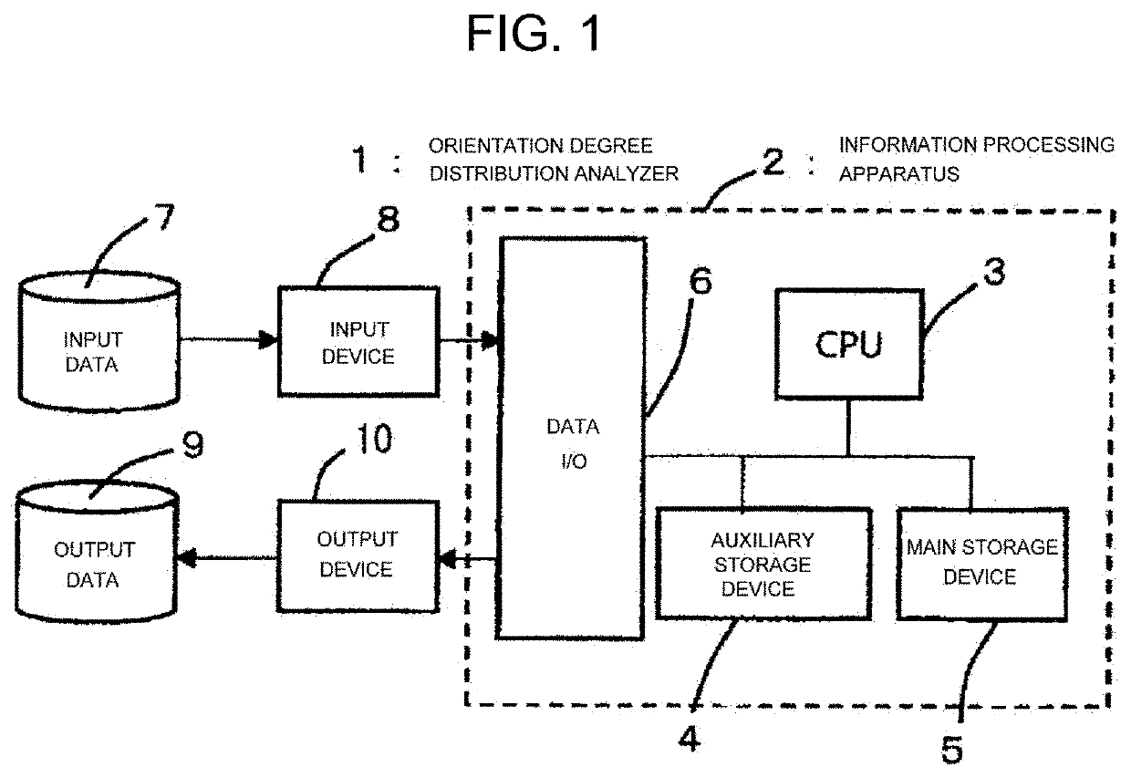
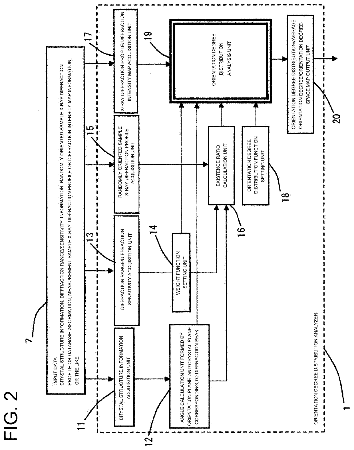
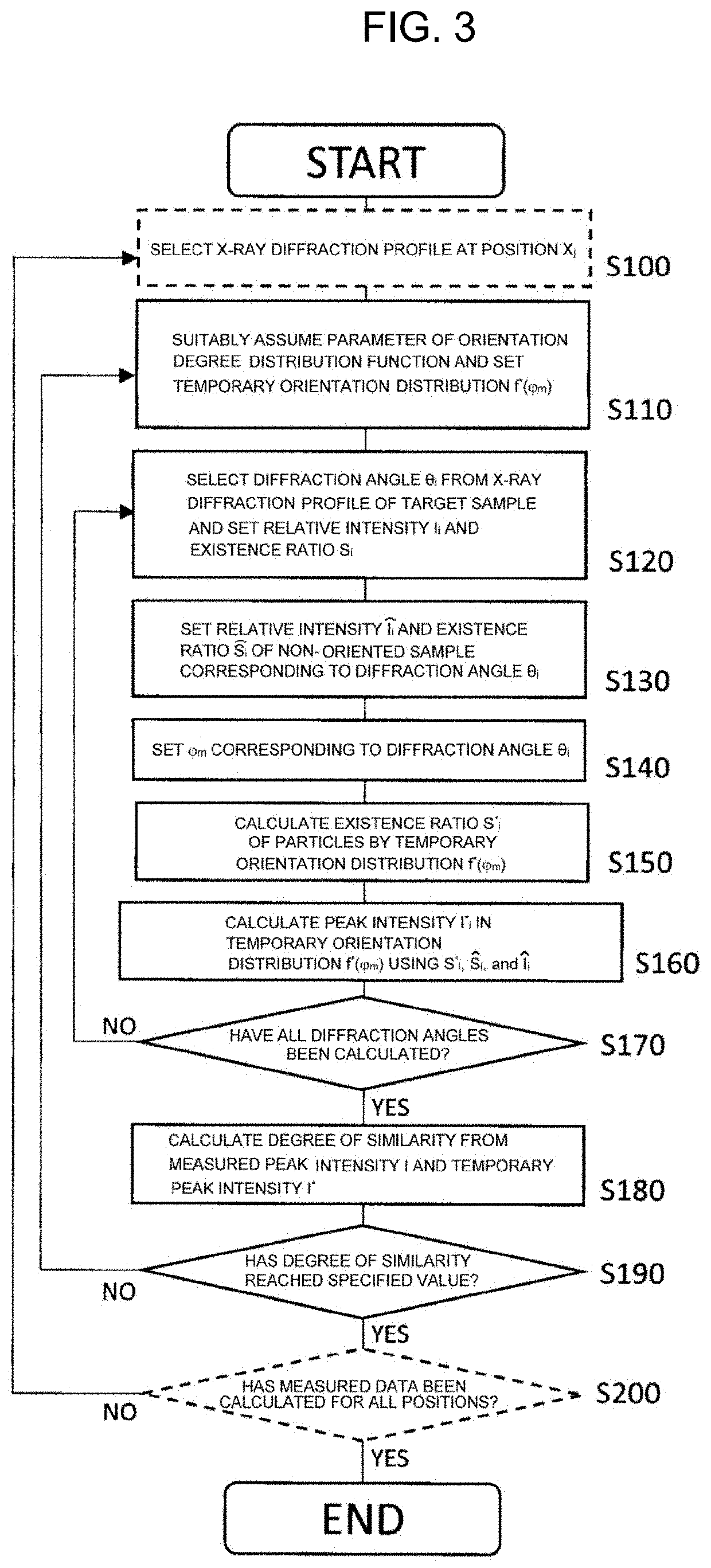

Image

  • Orientation degree distribution calculation method, orientation degree distribution analyzer, and orientation degree distribution analysis program
  • Orientation degree distribution calculation method, orientation degree distribution analyzer, and orientation degree distribution analysis program
  • Orientation degree distribution calculation method, orientation degree distribution analyzer, and orientation degree distribution analysis program

Examples


example 1

[0080]An example in which the orientation degree distribution calculation of the Sm2Fe17N3 bonded magnet is performed using the above orientation degree distribution calculation method will be described.

(Calculation of Angle φm Formed by Orientation Plane and Crystal Plane Corresponding to Diffraction Peak of Interest)

[0081]According to a PDF card of Sm2Fe17N3; (ICDD Card No.: 00-048-1790) (hereinafter, referred to as Non Patent Literature 2), the crystal structure of Sm2Fe17N3 is a rhombohedral crystal system, and the lattice constants are a=8.74 and c=12.66, respectively. From this data, Table 1 shows the results of calculating the angle (φm) formed by the orientation plane (in the case of this example, the (001) plane orthogonal to the c-axis which is the axis of easy magnetization) calculated using Formula (5) and the crystal plane corresponding to the diffraction peak of interest. In Table 1, calculation results for only peaks between diffraction angles of 30 to 60 degrees amon...

example 2

[0096]A case where the same Sm2Fe17N3 bonded magnet as that prepared in Example 1 is used as a measurement target, a diffraction intensity map is acquired using a micro-focal X-ray source, and spatial mapping of the orientation degree is performed will be described.

[0097]The measured sample was the same sample as Sample A in FIG. 7, the surface orthogonal to the orientation direction was manually polished with abrasive paper, and a part of the polished surface was measured using a micro-focal X-ray source (Panalytical Focusing X-ray lens 50 μm HR, hereinafter, referred to as a focusing lens).

[0098]The focusing lens is obtained by bundling several millions of glass capillaries each having a diameter of about 5 micrometers with light from an X-ray point light source, and is a device capable of obtaining a pseudo-parallel X-ray beam having a spot diameter of about 50 micrometers by guiding X-rays while totally reflecting the X-rays inside. The measured area was about 4 mm3, and the mea...


PUM


Abstract

An orientation degree distribution analysis method of the present invention includes steps of: inputting crystal structure information of an object to be measured, information on an intensity ratio of each diffraction peak and a crystal plane corresponding to each diffraction peak by X-ray diffraction measurement, information on a diffraction range and diffraction sensitivity, and an intensity ratio of each diffraction peak of a randomly oriented sample to a main storage device; calculating an angle formed by an orientation plane and a crystal plane corresponding to the diffraction peak of interest from the information stored in the main storage device in the step; calculating an existence ratio and storing the existence ratio in the main storage device; setting an orientation degree distribution function; and calculating an orientation degree distribution from the information of the input step and the calculation step. As a result, there are provided a method of easily calculating an orientation degree distribution from an X-ray diffraction profile by using an information processing apparatus and a calculation program without requiring complicated pretreatment of a sample as in an EBSD method, and a method of obtaining a spatial map of the orientation degree distribution from a plurality of diffraction intensity maps obtained by using a micro-focal X-ray.

Description

TECHNICAL FIELD[0001]The present invention relates to a technique for calculating a crystal orientation distribution of a sample from an X-ray diffraction profile (in the present specification, the X-ray diffraction profile refers to, for example, a list of diffraction angles corresponding to a certain crystal plane and relative intensities thereof obtained by measurement using an X-ray diffraction (XRD) apparatus, a powder diffraction file (PDF) card issued by the International Centre for Diffraction Data (ICCD), numerical calculation, or the like), and is particularly suitable for calculating an orientation degree distribution of a sample treated such that a certain crystal plane of a permanent magnet or the like is oriented in one direction.BACKGROUND ART[0002]Some materials have different characteristics depending on a crystal direction in which the material is constituted, and some materials are used by being treated (oriented) so that the crystal direction in the material is o...

Claims


Application Information

Patent Timeline
IPC IPC(8): G01N23/2055
CPCG01N23/2055
Inventor SODA, RIKIOOZAKI, KIMIHIRO
Owner NAT INST OF ADVANCED IND SCI & TECH
Learn More