Laser cooling system

a cooling system and laser technology, applied in semiconductor lasers, semiconductor/solid-state device details, lighting and heating apparatus, etc., can solve the problems of reducing power, compromising laser system performance, and increasing laser wavelength

Active Publication Date: 2018-03-01
NLIGHT INC
View PDF53 Cites 9 Cited by
  • Summary
  • Abstract
  • Description
  • Claims
  • Application Information

AI Technical Summary

Problems solved by technology

An increase in temperature may result in an increase in laser wavelength and decrease on power that may compromise a laser system's performance.

Method used


Image

  • Laser cooling system
  • Laser cooling system
  • Laser cooling system

Examples


Embodiment Construction

[0017]The present disclosure describes embodiments with reference to the drawing figures listed above. Persons of ordinary skill in the art will appreciate that the description and figures illustrate rather than limit the disclosure and that, in general, the figures are not drawn to scale for clarity of presentation. Such skilled persons will also realize that many more embodiments are possible by applying the inventive principles contained herein and that such embodiments fall within the scope of the disclosure which is not to be limited except by the claims.

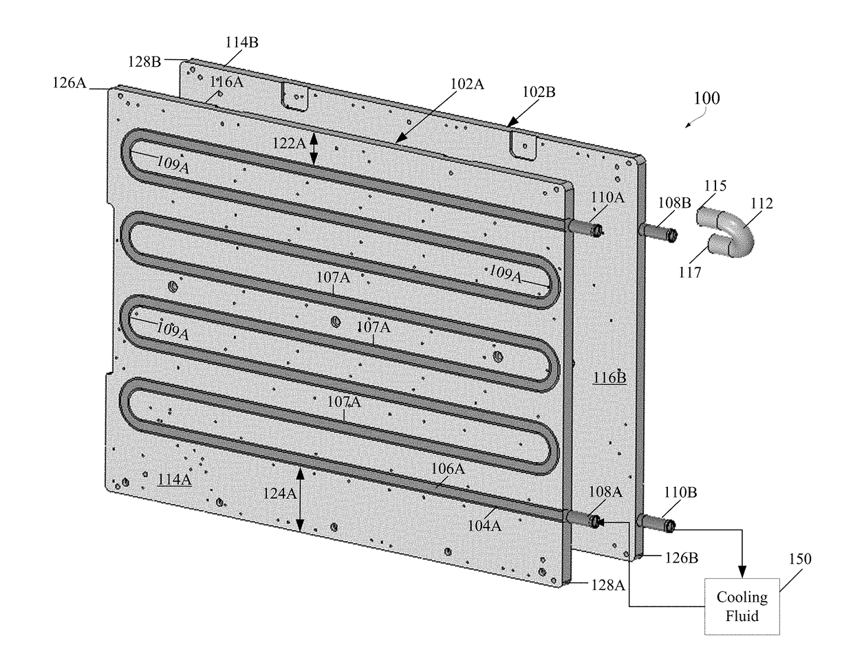
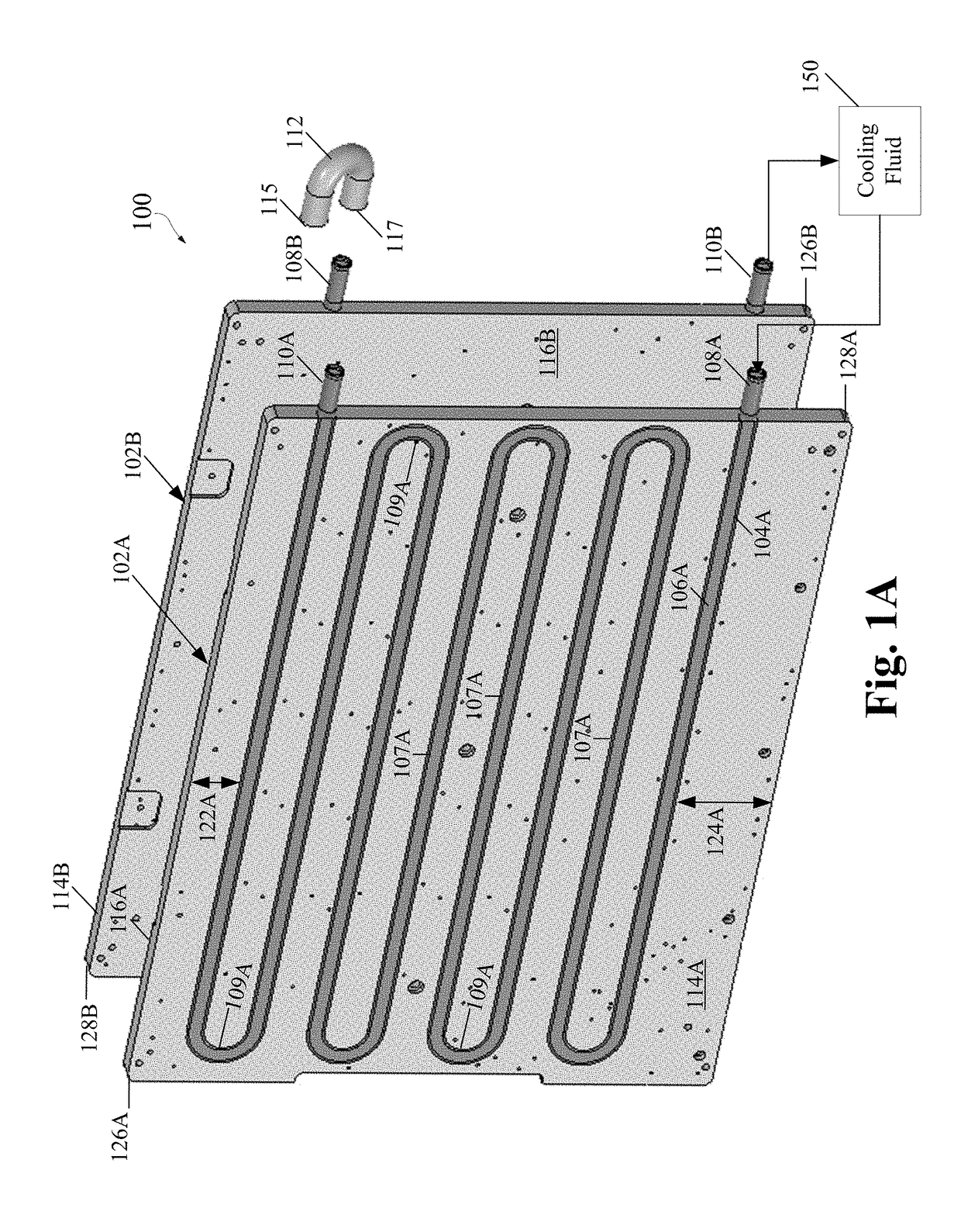
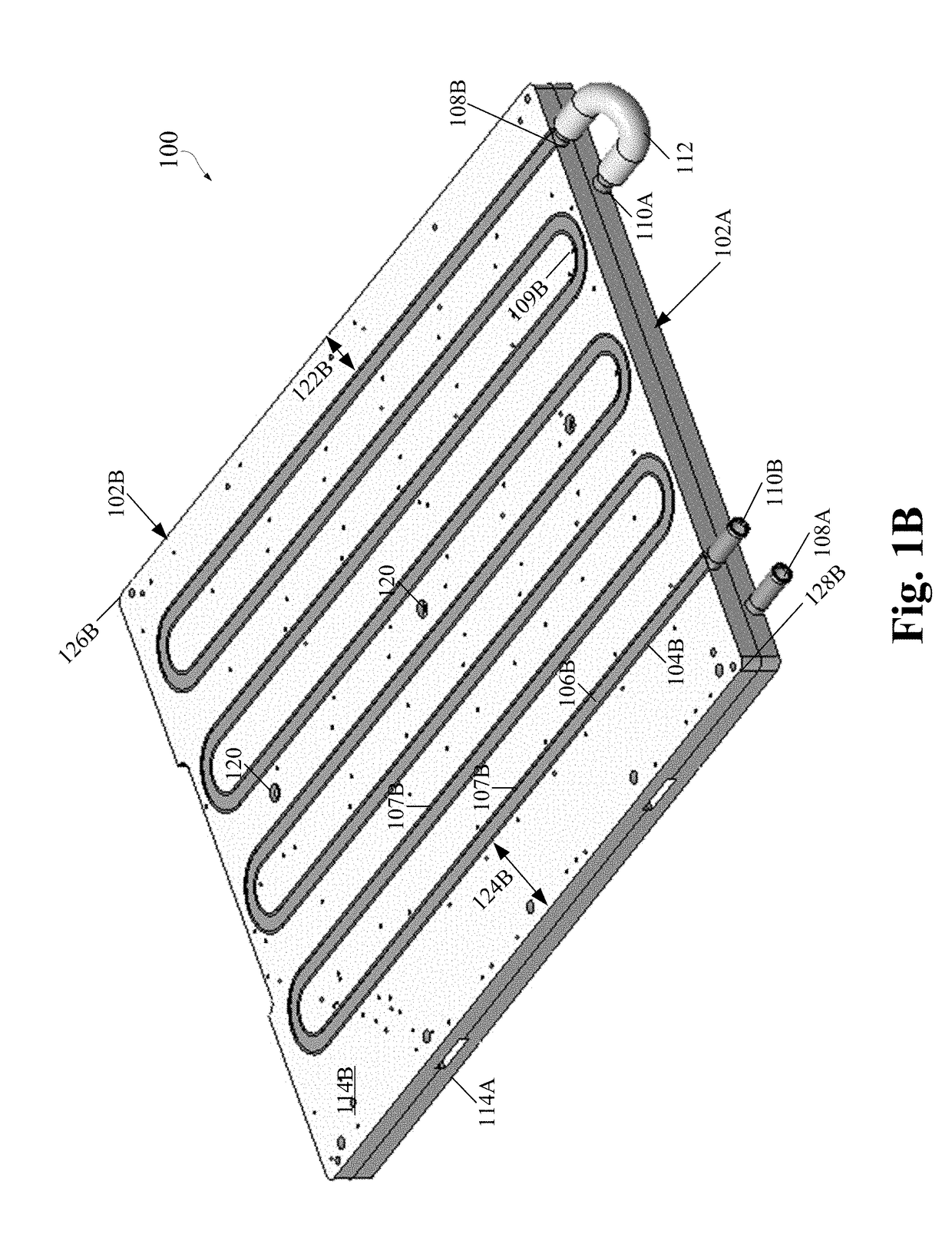
[0018]FIG. 1A diagrams an embodiment of an exploded view of a cooling system 100 according to the present disclosure. FIG. 1B diagrams an embodiment of an assembled view of cooling system 100 according to the present disclosure. Referring to FIGS. 1A and 1B, cooling system 100 may include a first cooling plate 102A and a second cooling plate 102B. First cooling plate 102A or second cooling plate 102B may have any shape known to...


PUM

PropertyMeasurementUnit
temperatureaaaaaaaaaa
optical conversion efficiencyaaaaaaaaaa

Abstract

A laser cooling system includes a first tubing, a second tubing, and a cold plate assembly including a first channel to receive the first tubing and a second channel to receive the second tubing. A joint removably couples the first tubing to the second tubing and at least one component mounted on the cold plate assembly over the first tubing or the second tubing. The inlet end of the first tubing receives a cooling fluid and an outlet end of the second tubing discharges the cooling fluid after the cooling fluid flows through the first tubing, the joint, and the second tubing to maintain uniform a temperature of the at least one component mounted on the cold plate assembly.

Description

RELATED APPLICATIONS[0001]This application is a non-provisional of and claims priority benefit to U.S. provisional application Ser. No. 62 / 382,034, filed Aug. 31, 2016, all of which is incorporated herein in its entirety.TECHNICAL FIELD[0002]The present disclosure relates to a laser cooling system.BACKGROUND[0003]The use of laser systems has become widespread in industrial, medical, and other applications. Laser systems may necessitate cooling to improve performance, avoid malfunction, and extend product life. As the amount of laser power increases so does the need to remove larger amounts of heat from the laser system to avoid overheating components that may change their operating characteristics. An increase in temperature may result in an increase in laser wavelength and decrease on power that may compromise a laser system's performance. Since the laser wavelength increases and power decreases with an increase in temperature, the temperature must be uniform throughout the system'...

Claims


Application Information

Patent Timeline
Patent Type & Authority Applications(United States)
IPC IPC(8): H01S5/024F28F9/013H01S3/04F28D15/04B23K26/70H01L23/473
CPCH01S5/02423F28F9/0131H01S3/0402F28D2021/0028B23K26/703H01L23/473F28D15/04F28D15/00F28D15/0275F28F1/22H01S5/02438H01S5/4025F28D2021/0029F28D1/0477F28D1/0435F28F2210/10F28F3/12
Inventor HODGES, AARON LUDWIGSTEPHENS, RODNEY MARK
Owner NLIGHT INC
Why Eureka
Try Eureka