

Base station, terminal, and communication method
- Summary
- Abstract
- Description
- Claims
- Application Information
AI Technical Summary
Benefits of technology
Problems solved by technology
Method used
Image


Examples
first embodiment
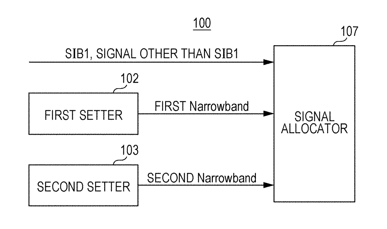
[0033]A default offset is set to the Narrowband in which MTC SIB1 is placed, and PRB included in the Narrowband is defined based on the default offset which is set. In addition, definition of Narrowband for MTC resources other than MTC SIB1 is notified via MTC SIB1. The notification is made in the form of additional offset from the default offset. When no change is made from the default offset, the notification includes a parameter indicating that a predetermined offset is not changed. In this manner, since the default offset is specified in advance, an MTC terminal is able to receive SIB1 for MTC without receiving the definition of Narrowband. Also, the data other than MTC SIB1 may not be changed when the predetermined offset works, or may be changed when the predetermined offset is desired to be changed.
Operations
[0034]The base station and the MTC terminal share the definition of Narrowband in which MTC SIB1 is placed in advance. Table illustrates an example of a method of setting...
second embodiment
[0064]In this embodiment, when the definition of Narrowband of an MTC SIB1 and the definition of Narrowband of another signal are different, an MTC terminal with many repetitions does not receive signals other than MTC SIB1 and MIB in a subframe in which MTC SIB1 is placed. The subframe in which MTC SIB1 is placed is used for retuning for frequency hopping. In this manner, the definition of Narrowband does not have to be changed for each subframe during data reception. Also, using a subframe with a different definition of Narrowband for retuning achieves allocation in which a subframe for retuning does not have to be set separately.
Precondition and Summary of Second Embodiment
[0065]In addition to a terminal with a line quality equivalent to the line quality of a terminal in related art, the MTC terminals include an MTC terminal which is disposed in the underground of a building and has an extremely low line quality. In order to serve for terminals with a low line quality, enhancemen...
operation example 1
of Large Repetition
Frequency Hopping Period of 5 for FDD
[0069]FIG. 11 is a diagram illustrating an example of FDD with a frequency hopping period of 5. It is assumed that MTC SIB1 is placed on subframe #4 of Frame #1. In the case of a frequency hopping period of 5 of MTC terminal, switching of the frequency hopping for DL is set to subframe #4 and 5th subsequent subframe, that is, subframe #9 in which an MTC SIB may be placed. The MTC terminal receives a signal by the same Narrowband for subframe #0 to subframe #3, performs retuning on the subframe #4, and receives a signal by the same Narrowband for subframe #5 to subframe #8.
[0070]In FIG. 11, the MTC terminal receives a signal by Narrowband #0 for subframe #0 to subframe #3 of Frame #1, receives a signal by Narrowband #2 for subframe #5 to subframe #8, receives a signal by Narrowband #1 for subframe #0 to subframe #3 of Frame #2, and receives a signal by Narrowband #3 for subframe #5 to subframe #8. The definition of Narrowband is...
PUM
 Abstract
Description
Claims
Application Information